


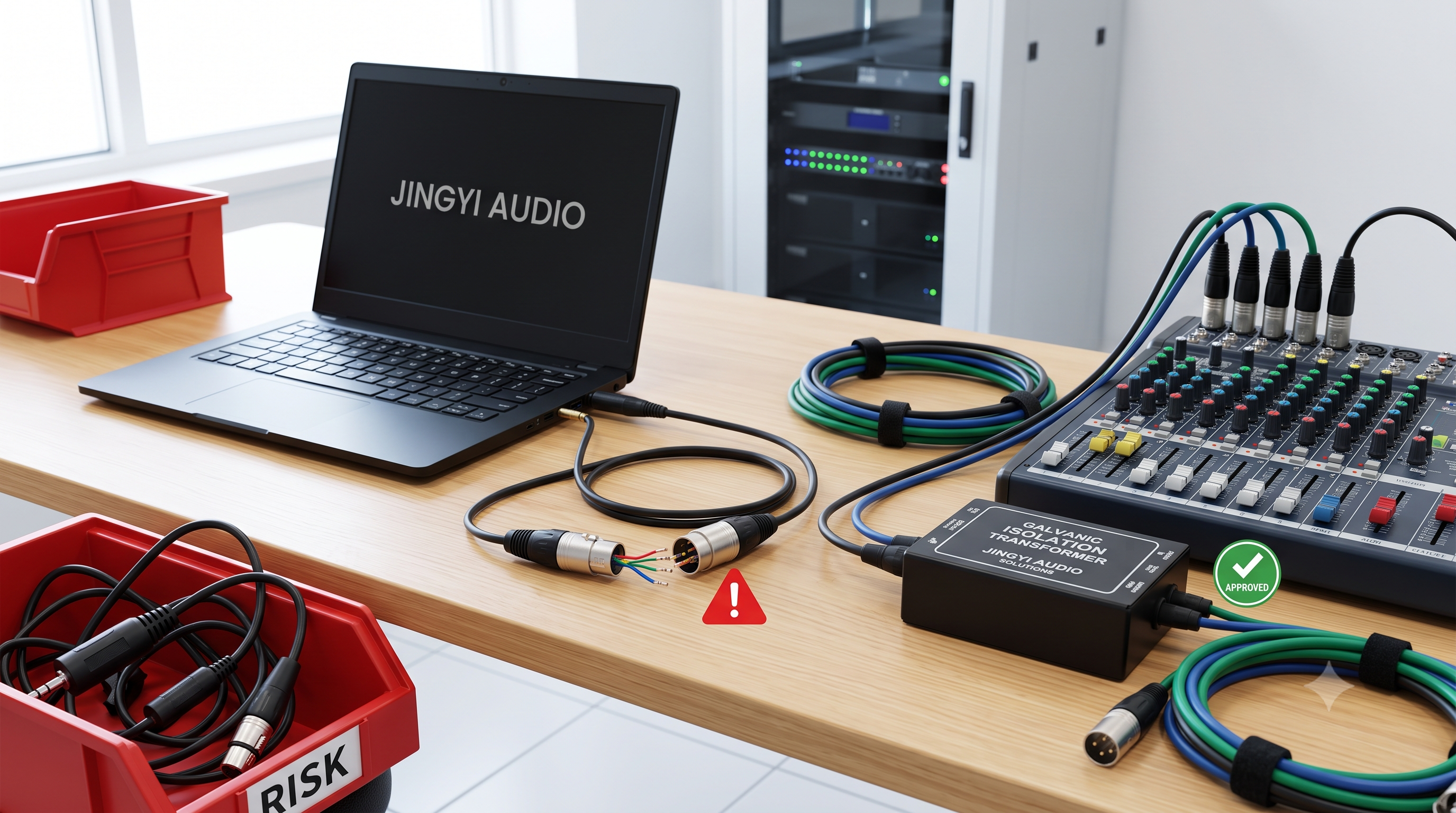
The Technical Guide to 25 ft 3.5 mm Audio Cables in B2B AV Integration
Author: Lynn Zhang, CEO at Jingyi Audio
Published: June 8, 2026 | Category: AV Engineering & Procurement | Read Time: 18 mins | Editorial Status: Peer-Reviewed Technical Whitepaper
Author Biography & Editorial Authority
Lynn Zhang is the founder and CEO of Jingyi Audio, an industry-leading B2B provider of commercial-grade acoustic solutions, professional DSP routing architectures, and high-integrity cabling installations. With over 15 years of field experience designing and commissioning enterprise-level conference layouts, education spaces, and municipal broadcast hubs, Lynn's expertise bridges the gap between material physics and high-yield procurement.
This technical guide has been verified against the latest National Electrical Code (NEC) standards, electrophysical formulas, and real-world commercial integrator incident reports.
- Introduction: The 25-Foot Challenge in Commercial Audio
In commercial audiovisual (AV) integration, routing analog line-level audio over a distance of $25 \text{ ft}$ ($7.62 \text{ m}$) represents a critical operational juncture where physical layout, safety regulations, and electronic performance converge. Boardrooms, educational lecture halls, and corporate training facilities frequently rely on $3.5\text{ mm}$ TRS (Tip-Ring-Sleeve) analog connections to interface host laptops, legacy media players, and mobile devices with professional amplifiers, active speakers, or conferencing codecs.
However, because standard $3.5\text{ mm}$ audio lines are inherently unbalanced, running them over a 25 ft 3.5 mm audio cable path exposes the signal to electrophysical attenuation, electromagnetic interference, and ground loop anomalies.
This guide provides procurement officers, system integrators, and IT administrators with an exhaustive technical analysis of $25\text{-foot}$ $3.5\text{ mm}$ audio cables, incorporating real-world field experiences from professional forums, material compliance standards, and advanced troubleshooting methodologies.
- Market Analysis: Selecting the Right Commercial-Grade 25 ft 3.5 mm Audio Cable
To optimize system reliability and control total cost of ownership (TCO), B2B procurement must distinguish between different commercial tier-group products. Commercial-grade audio cables vary significantly based on shielding efficiency, jacket fire ratings, conductor material, and strain-relief designs.
Distinguishing Consumer Grades from Enterprise-Grade Hardware
Consumer auxiliary cables are designed for short-term, low-flex desktop environments. In contrast, enterprise deployment demands materials that resist mechanical fatigue, comply with municipal fire codes, and prevent electromagnetic ingress when run alongside AC electrical lines.
Below is a comparative analysis of leading $25\text{-foot}$ cabling solutions designed for enterprise deployment, revealing distinct hardware philosophies and targeted application contexts:
|
Procurement Parameter |
C2G Plenum-Rated 3.5mm (Part: 40516) |
Tripp Lite Mini-Stereo Cable (Part: P312-025) |
Kramer C-MDMA/MGMA-25 Breakout Cable |
Liberty AV Open Plenum Audio (Part: P221P-3.5TRSM-T-50) |
Bafx Shielded Extension Cable (Part: BAFX3417) |
|
Primary Target Application |
In-wall/ceiling routing in commercial and educational environments. |
Standard desktop patching and multimedia bridging. |
High-density laptop to video conferencing system integration. |
Plenum patching line-level stereo audio into Phoenix connectors/terminal blocks. |
IR repeater extensions and low-voltage auxiliary routing. |
|
Connector Gender / Configuration |
$3.5\text{ mm}$ Stereo Male-to-Male. |
$3.5\text{ mm}$ Stereo Male-to-Male. |
$3.5\text{ mm}$ Stereo + VGA (15-pin HD) to DVI Breakout. |
$3.5\text{ mm}$ Stereo Male to unterminated open end (cut to measure). |
$3.5\text{ mm}$ Stereo Male-to-Female Extension. |
|
Jacket Material & Fire Safety Rating |
Kynar PVDF / CMP (Plenum-Rated). |
Standard PVC / Non-Plenum. |
Standard PVC / Non-Plenum. |
UL CMP, C(UL) CMP FT6 (Plenum-Rated). |
Protective Flexible PVC / Non-Plenum. |
|
Conductor Construction & Gauge |
Three $75\text{-Ohm}$ coaxial paths with $26 \text{ AWG}$ center conductors. |
Standard Copper stranded conductor. |
Multi-conductor stranded copper breakout. |
$22 \text{ AWG}$ Twisted, shielded broadcast audio cable. |
Standard 3-pin round shielded copper. |
|
Shielding Architecture |
Tinned copper braid providing $92\%$ coverage over foil shield. |
Double-molded strain relief with standard shielding. |
Heavy-duty molded unbalanced shield jacket. |
Twisted pair with internal shielding. |
Braided / stranded protective shield. |
|
Connector Finish & Material |
Gold-plated low-profile connectors ($1.5\text{-inch}$ depth). |
Gold-plated high-conductivity connectors. |
Molded nickel/gold contacts with rugged boots. |
Silver solder contacts at the $3.5\text{ mm}$ plug end. |
Sturdy molded jacks with reinforced collar. |
|
Average B2B Unit Cost Range |
$\$42.00$ – $\$49.99$ |
$\$6.50$ – $\$9.00$ |
$\$35.00$ – $\$38.00$ |
$\$45.00$ – $\$55.00$ (per 50ft reel) |
$\$10.00$ – $\$14.00$ |
When Copper Lines Fail: The Ultra-High-Bandwidth Fiber-Optic Alternative
For ultra-critical, high-bandwidth broadcast applications requiring zero susceptibility to electromagnetic fields, copper lines are sometimes bypassed entirely. In these highly specialized environments, integrators specify broadcast-grade fiber-optic lines, such as the Camplex SMPTE Hybrid FMW/PUW LEMO Belden indoor fiber cable. Operating with bandwidth support of $19.4 \text{ Mbps}$ to $3 \text{ Gbps}$ and return loss under $-55 \text{ dB}$, such optical lines demonstrate the physical upper limits of isolated signal routing when standard copper runs cannot guarantee signal integrity.
- Electrophysical Performance: What Happens to Analog Signals at 25 Feet?
Deploying an unbalanced analog line over a $25\text{-foot}$ path introduces multiple physical and electrical issues that directly affect sound quality. Understanding these underlying electromagnetic mechanisms is essential for engineering robust commercial audio systems.
Series Resistance and Voltage Drop
Electrical resistance ($R$) in an audio conductor is a function of the conductor's material resistivity ($\rho$), length ($L$), and cross-sectional area ($A$), expressed mathematically as:
$$R = \rho \frac{L}{A}$$
Because B2B installations utilize thin cables to maximize conduit space, conductors are typically engineered at $24 \text{ AWG}$ to $28 \text{ AWG}$. Over a $25\text{-foot}$ run, the cumulative series resistance of these small-gauge lines attenuates low-voltage line-level signals. At line-level impedances, this resistance causes a measurable voltage drop, reducing the signal-to-noise ratio before the audio reaches the preamplifier stage.
At speaker-level, resistance is even more critical; output levels and amplifier damping factors degrade when cable resistance exceeds approximately $5\%$ of the speaker's rated impedance. For typical $8\text{-ohm}$ commercial monitors, $16 \text{ AWG}$ is recommended for runs up to $50 \text{ ft}$, but at line-level, thin $3.5\text{ mm}$ cables must rely on high input impedance at the receiving end to prevent signal loss.
Cumulative Capacitance and High-Frequency Attenuation (The Low-Pass Filter)
An analog audio cable acts as a continuous capacitor. The parallel signal conductors, separated by an insulating dielectric jacket, accumulate and store an electrical charge. This cable capacitance ($C$), in combination with the output impedance ($R_{\text{out}}$) of the source device (such as a laptop motherboard), creates a first-order low-pass filter. The cutoff frequency ($f_c$) of this filter is defined as:
$$f_c = \frac{1}{2 \pi R_{\text{out}} C}$$
As cable length increases to $25 \text{ ft}$ and beyond, cumulative capacitance rises proportionally. While low-impedance professional outputs mitigate this effect, high-impedance legacy sources under heavy capacitive load suffer a significant "roll-off" of high frequencies, which reduces the clarity, crispness, and speech intelligibility of the audio signal.
Unbalanced Shielding: Why 25 Feet of Copper Acts as an Antenna
In balanced professional audio runs, common-mode rejection utilizes two polarity-inverted signal wires and a separate ground to cancel out environmental noise. Conversely, a standard $3.5\text{ mm}$ TRS connection is unbalanced. It uses single signal lines for the left and right channels, while using the outer metallic shield as both the electrostatic ground and the active signal return path.
Because the shield carries the return signal, any noise induced into it by external electromagnetic fields (EMI) or radio-frequency interference (RFI) is directly summed into the audio signal. At a length of $25 \text{ ft}$, the cable acts as an antenna, picking up ambient noise from fluorescent ballasts, old stage dimmers, and power distribution lines.
- Conductor Metallurgy: OFC vs. CCA
The choice of conductor material dictates a cable's longevity, electrical stability, and signal integrity over its operational lifespan. B2B specifications must rigorously distinguish between Oxygen-Free Copper (OFC) and Copper-Clad Aluminum (CCA).
|
Performance Vector |
Oxygen-Free Copper (OFC) Conductor |
Copper-Clad Aluminum (CCA) Conductor |
|
Metallurgical Composition |
Pure copper processed to reduce oxygen content to $<0.001\%$. |
Aluminum core clad with an outer layer of copper. |
|
Electrical Conductivity |
Maximum ($100\%$ IACS equivalent). |
Lower; requires larger gauges to match copper conductivity. |
|
Mechanical Fatigue Resistance |
Highly durable; resists copper fatigue under repeated flexing. |
Prone to stress fractures, bending damage, and brittleness. |
|
Oxidation and Corrosion |
Resistant to oxidation; maintains low contact resistance. |
Prone to galvanic corrosion if the copper cladding is breached. |
|
Weight Profile |
Standard industrial weight; less flexible in heavy gauges. |
Lightweight; highly flexible for temporary setups. |
|
B2B Lifecycle Valuation |
High upfront cost offset by long-term system stability. |
Low upfront cost; prone to high replacement frequency. |
The Cost of Mechanical Fatigue in High-Use Commercial Zones
Under high-use commercial conditions, such as cables routed through articulated desk-access hatches or retractable table enclosures, CCA conductors degrade rapidly. Repeated physical stress causes micro-fractures in the aluminum core, resulting in unexpected signal dropouts, channel imbalances, and increased resistance. Therefore, specifications for long permanent B2B installations must choose high-purity OFC conductors to maintain system reliability and prevent costly truck rolls.
- Regulatory Compliance and Fire Codes for In-Wall Integrations
Permanent installations of low-voltage cabling in commercial structures are strictly regulated by safety codes, such as the National Electrical Code (NEC) in the United States or the Canadian Standards Association (CSA) standards. System integrators must evaluate the environment's airflow path to determine if Plenum-rated cabling is legally mandated.
Demystifying the Plenum Space
Plenum spaces are the areas above suspended ceilings, below raised floors, or inside air ducts used to circulate environmental air throughout a building. Because these zones act as shared air pathways, a fire originating in one room can rapidly spread toxic smoke and flames throughout the entire facility via standard cabling. To mitigate this hazard, building codes dictate that any cabling run through a plenum space without a surrounding metal conduit must be CMP (Communications Plenum) certified.
The Chemical Difference: CMP Fluoropolymers vs. Standard PVC
Standard non-plenum cables utilize polyvinyl chloride (PVC) jackets, which emit dense, corrosive hydrochloric acid fumes and thick black smoke when ignited. CMP-rated cables, such as the C2G 40516, are engineered using specialized high-temperature fluoropolymer compounds:
- Insulation Layer: Conductors are wrapped in fluorinated ethylene propylene (FEP), which exhibits excellent dielectric properties and a very high melting point.
- Outer Jacketing: The exterior sheath is composed of Kynar (a polyvinylidene fluoride / PVDF copolymer) or low-smoke PVC, which resists flame propagation and limits the release of toxic, sight-obscuring gases.
For in-wall and ceiling installations in hospitals, schools, and corporate office complexes, B2B procurement must mandate CMP-rated $3.5\text{ mm}$ cabling. This ensures strict compliance with fire safety laws and eliminates the labor and material costs associated with running rigid metal conduits.
- Field Case Studies: Real-World Failures & Expert Workarounds
Real-world deployment experiences documented by system engineers on LinkedIn and Reddit's professional audio communities (r/livesound, r/CommercialAV, and r/audio) reveal that long, unbalanced $3.5\text{ mm}$ auxiliary runs are a frequent source of technical issues.
Case Study 1: Switch-Mode Charger Interference on Presenter Tablets
A common problem discussed in B2B systems integration groups on LinkedIn involves using standard $25\text{-foot}$ $3.5\text{ mm}$ cords to connect podium-mounted iPads or Android tablets to main mixers. Integrators report that these tablets are dead quiet when running on battery power. However, as soon as the tablet is connected to its wall charger, a loud high-frequency buzz or whine is introduced into the PA system.
The charger's switch-mode power supply (SMPS) injects common-mode noise into the tablet’s ground bus. Because the headphone jack uses an unbalanced output, this noise is carried directly along the cable's ground shield. In this scenario, standard passive direct boxes with a ground lift often fail to eliminate the noise because high-frequency switcher harmonics ($30 \text{ kHz}$ to $500 \text{ kHz}$) bypass the transformer via inter-winding capacitance.
The Solution: Integrators must bypass the analog headphone jack entirely, utilizing either a USB-C class-compliant audio interface with balanced outputs or a phantom-powered Bluetooth receiver connected to the console.
Case Study 2: Custom Shield Ground Lifts in PC-to-Mixer Corporate Runs
In a corporate boardroom installation discussed on r/CommercialAV, an engineer encountered severe ground loop buzz when connecting a desktop PC’s rear line-out port to an external audio controller card over a $25\text{-foot}$ line. Standard, cheap $3.5\text{ mm}$ extension cables, which use thin plastic-coated stranded wires, offered very poor noise rejection.
[Corporate PC Chassis Ground] [Audio Controller Ground]
| |
+===> (Ground Loop Current Flows Through Cable Shield) <===+
|
[Resulting 60Hz Hum in Audio Output]
|
[Custom Integrator Workaround]
|
[Computer Side: Shield Connected] ==================> [Controller Side: Shield Floating / Cut]
The Solution: To solve the loop without purchasing active converters, the integrator custom-built a $3.5\text{ mm}$ cable where the ground shield was soldered only on the computer side, leaving the destination end floating. This modification successfully broke the ground path between the PC chassis and the audio controller, eliminating the loop while allowing the signal to pass cleanly.
Case Study 3: Mechanical Jack Tension Loss in Classrooms
An installer on r/audio documented a high failure rate of cheap $25\text{-foot}$ male-to-female $3.5\text{ mm}$ extension cables used in school classrooms. While these extension lines worked flawlessly out of the box, teachers reported that after a few weeks, the audio would cut out or play only in one channel unless the connector was held at a specific angle.
The Solution: The female spring connectors inside the cheap molded jacks had lost their physical tension after repeated insertion cycles, creating a high-resistance contact point. This mechanical failure can be prevented by specifying professional-grade cables with single-piece, reinforced metal housings and heavy-duty strain reliefs. These heavy-duty connectors are designed to withstand physical stress and maintain strong contact pressure over thousands of mating cycles.
- Actionable Recommendations for B2B Systems Procurement
Based on field performance data and commercial compliance standards, the following guidelines should be implemented in B2B procurement policies and AV system designs:
- Enforce Safety Compliance for Air-Handling Pathways: Ensure that any $3.5\text{ mm}$ analog cabling routed through drop ceilings, raised floors, or in-wall air spaces is CMP (Plenum) rated. Using non-compliant PVC cables in these areas violates building safety codes and poses significant legal and fire hazards.
- Standardize on Pure OFC Copper Conductors: Avoid purchasing cheap Copper-Clad Aluminum (CCA) cables for permanent corporate or educational systems. Standardizing on high-purity Oxygen-Free Copper (OFC) ensures long-term resistance to physical stress, prevents galvanic corrosion, and avoids high replacement costs.
- Bypass Headphone Jacks with Dedicated USB-C Interfaces: For high-traffic areas like conference room podiums, stop using standard $3.5\text{ mm}$ analog audio cables. Instead, provide desktop USB-C DAC interfaces connected to the audio system via balanced XLR runs. This keeps the analog signal path short, isolates ground loops, and delivers consistent, noise-free sound.
- Install Isolated Transformers for Legacy Analog Lines: If a system must use a $25\text{-foot}$ analog $3.5\text{ mm}$ cable, install a high-performance stereo isolation transformer with built-in Faraday shielding (such as the RDL AV-HK1) at the destination end. This breaks the ground path and prevents switch-mode power supply hum from entering the system.
- Use Proper Balanced Conversion for Long Runs: Do not route unbalanced analog signals over distances greater than $25 \text{ ft}$. If longer distances are required, use active $3.5\text{ mm}$-to-balanced XLR converters, active audio over Cat5e/Cat6 baluns, or optical fiber bridges near the source device.
- Frequently Asked Questions (FAQ)
Q1: How does a 25 ft 3.5 mm audio cable run affect high-frequency roll-off and impedance matching in high-density office installations?
Short Answer: A 25-foot run creates an unplanned low-pass filter that can muffle treble frequencies and reduce speech clarity, especially when connected to high-impedance legacy amplifiers.
The electrophysical interaction of line-level source impedance with high-capacitance cabling creates an unplanned low-pass filter. Standard consumer electronics (laptops, mobile tablets) feature output impedances ranging from $10 \text{ to } 100 \text{ }\Omega$. When these devices drive a 25 ft 3.5 mm audio cable, which has a nominal cumulative capacitance of approximately $30 \text{ to } 40 \text{ pF}$ per foot, the low-pass cutoff frequency ($f_c$) typically remains above $1 \text{ MHz}$. This preserves the standard $20 \text{ Hz}$ to $20 \text{ kHz}$ audio spectrum without audible degradation.
However, if the cable is routed to a high-impedance input device (such as legacy corporate amplifiers with input impedances exceeding $10\text{k }\Omega$) or connected to a passive high-impedance source, the high-frequency roll-off drops sharply. In these scenarios, high-frequency harmonics are attenuated, causing speech to sound muffled and reducing the clarity of multimedia presentations.
To preserve audio quality across variable sources, B2B system designs must keep analog runs as short as possible. Alternatively, integrators can use active buffer amplifiers or digital conversion paths (such as USB-C to balanced XLR interfaces) to lower the effective drive impedance and eliminate cable-induced filtering.
Q2: Why does a laptop connected via a 25 ft 3.5 mm audio cable generate a high-frequency whine when charging, and why do standard 1:1 ground isolation transformers sometimes fail to resolve it?
Short Answer: High-frequency switching noise from the laptop charger leaks directly onto the unbalanced cable shield, bypassing standard ground isolators via inter-winding capacitance.
This distinct high-frequency whine is caused by common-mode noise generated by the laptop’s switch-mode power supply (SMPS). Laptop chargers operate by rapidly switching AC voltage at frequencies ranging from $30 \text{ kHz}$ to $500 \text{ kHz}$, creating high-frequency electrical noise and harmonics on the DC ground bus. Because the 25 ft 3.5 mm audio cable is unbalanced, this charger-induced noise is imposed directly onto the audio ground shield, corrupting the low-voltage analog signal.
[Mains AC Power] -> [Laptop SMPS Charger (30k-500kHz Switch Noise)]
|
(Noisy DC Ground)
|
[Laptop Motherboard] -> [25ft Unbalanced 3.5mm Cable] -> [Traditional 1:1 Transformer] -> [Amp]
| |
(Common-Mode Noise) (High Inter-Winding Cap)
| |
+---> [Noise Leaks Past Transformer] --+
v
[Audible High-Freq Whine]
Traditional 1:1 passive audio isolation transformers are designed to break ground loops at the $50 \text{ Hz}$ or $60 \text{ Hz}$ mains frequency. They often fail to isolate SMPS whine because of inter-winding capacitance. The high-frequency noise of the SMPS charger bypasses the magnetic core of the transformer, coupling directly from the primary winding to the secondary winding via electrostatic capacitance.
To resolve this issue, integrators should deploy high-grade isolation systems featuring electrostatic Faraday shields between the transformer windings, such as the RDL AV-HK1. Alternatively, they can completely bypass the analog ground path by using an external USB DAC or a wireless Bluetooth bridge.
Q3: What are the electrical and audio consequences of using passive Y-splitters or direct "stereo-to-balanced XLR" adapter cables with a 25 ft 3.5 mm audio cable in boardroom mixer integrations?
Short Answer: This setup triggers phase cancellation that strips away vocals and center-panned sounds, while forcing low-impedance source outputs to fight and overheat.
Using a simple adapter cable to connect a $3.5\text{ mm}$ stereo output to a balanced mono XLR input on a commercial mixer creates a phase cancellation trap. A balanced XLR input expects a single differential mono signal: the "hot" positive phase on Pin 2 and the "cold" negative phase on Pin 3. When a standard stereo-to-XLR adapter is used, the left channel is routed to Pin 2 and the right channel is routed to Pin 3.
[3.5mm Stereo Source] [Balanced Mono XLR Input]
Tip (Left Channel) ==============================> Pin 2 (Hot / Positive Phase)
Ring (Right Channel) ==============================> Pin 3 (Cold / Negative Phase)
Sleeve (Ground) ==============================> Pin 1 (Shield / Ground Reference)
Resulting Signal = Left - Right (Phase Cancellation of Mono and Center-Panned Audio)
The differential receiver at the XLR input subtracts the cold signal from the hot signal to eliminate common-mode noise, processing the input according to the equation:
$$\text{Signal} = \text{Left} - \text{Right}$$
This subtraction cancels out any audio information that is identical in both channels (such as vocals, center-panned speech, and mono bass). This results in thin, hollow sound, missing audio elements, and high distortion.
Additionally, using a passive Y-cable to combine the left and right outputs of a $3.5\text{ mm}$ source into a single mono input forces the low-impedance output op-amps of the source device to fight each other. Each channel attempts to drive the other's output circuit, causing signal distortion, increased heat generation, and potential long-term hardware damage.
To prevent this, B2B integrations must split the stereo signal into two separate mixer channels using a stereo breakout cable, utilize a resistor-based passive summing network, or route the signal through a transformer-isolated stereo-to-mono direct box.
Q4: When does commercial code require CMP-rated (Plenum) 25 ft 3.5 mm audio cables, and what are the physical structural differences compared to standard PVC-jacketed lines?
Short Answer: Building codes require plenum-rated cables whenever wiring runs through open air-handling spaces like drop ceilings or raised floors without metal conduit.
Commercial building codes and the National Electrical Code mandate CMP-rated (Plenum) cabling whenever low-voltage wiring is routed through environmental air-handling spaces without being enclosed in a continuous metal conduit. These air-handling spaces include the areas above drop-tile ceilings and beneath raised flooring systems commonly used for cable management in modern office spaces.
Structurally, standard 25 ft 3.5 mm audio cables utilize flexible, combustible PVC jackets that release dense smoke and acidic hydrogen chloride gas when exposed to fire. In contrast, CMP-rated cables use advanced fluoropolymers, such as fluorinated ethylene propylene (FEP) for internal wire insulation and polyvinylidene fluoride (PVDF/Kynar) for the outer jacket.
These materials have extremely high melting points, resist ignition, and emit very little smoke. Additionally, CMP-rated cables like the C2G 40516 feature high-density shielding, such as a $92\%$ tinned copper braid over aluminum foil, to protect against electrostatic noise in packed ceiling conduits.
Q5: How can B2B integrators differentiate between electromagnetic/radio-frequency interference (EMI/RFI) and true ground loop hum on a 25 ft 3.5 mm audio cable line?
Short Answer: Move the cable: if the noise level changes, the issue is EMI/RFI ingress; if the hum remains completely constant, it is a ground loop.
To troubleshoot noise on a 25 ft 3.5 mm audio cable analog path, integrators must isolate the physical and electrical characteristics of the interference. A true ground loop hum is caused by small electrical voltage differences between the grounds of two connected devices. This ground loop creates a continuous, low-frequency hum at the local mains frequency ($60 \text{ Hz}$ in North America or $50 \text{ Hz}$ in Europe and Asia) along with its lower harmonics.
In contrast, EMI and RFI are induced into the cable from external sources and present a wider variety of sounds. High-frequency buzzes, clicks, crackles, and whistling are typically caused by PC motherboards, graphics cards under load, or nearby network cables. RFI can also manifest as demodulated AM/FM radio transmissions or high-frequency static.
[Diagnostic Test: Physical Cable Repositioning]
|
+--------------------------+--------------------------+
| |
[Noise Level / Pitch Changes] [Noise Remains Constant]
| |
Indicates: EMI / RFI Ingress Indicates: Ground Loop Hum
- Induced from external sources. - Caused by ground potential differences.
- Requires: Shield upgrade, route - Requires: 1:1 isolation transformer,
separation, or ferrite chokes. ground-lift, or balanced conversion.
To diagnose the issue, integrators can use three simple diagnostic tests:
- Physical Cable Repositioning: Move the $25\text{-foot}$ cable away from power strips, chargers, and network runs. If the noise level changes, the issue is EMI/RFI ingress.
- The Touch Test: Touch the metal chassis of the amplifier or mixer. If the buzz quiets down, it indicates the system has insufficient grounding or shielding, allowing the user's body to act as an antenna.
- Ground Separation: Temporarily disconnect the source device's charger and run it on battery power. If the noise disappears, the system has a charger-induced ground loop.
To resolve EMI/RFI issues, use double-shielded cables with woven braids, separate audio runs from AC lines, or clip on ferrite chokes. For ground loop hums, install a 1:1 stereo isolation transformer or convert the unbalanced signal to a balanced line near the source.
- Conclusion
Deploying a 25 ft 3.5 mm audio cable in a professional B2B environment is not as simple as picking a cheap auxiliary cord off a retail shelf. As technical managers, designers, and procurement professionals, ensuring high performance means respecting physical laws and building safety regulations.
By avoiding copper-clad aluminum (CCA), enforcing communication plenum (CMP) requirements for in-ceiling conduits, and understanding when to transition to active balanced solutions (such as USB-C interfaces or active baluns), integrators can design silent, reliable, and compliant audio spaces. Ensure your upcoming requests for proposal (RFPs) and bill of materials (BOMs) protect your clients and installations from electrophysical degradation.