




What is an XLR Input? Pinouts, Audio Physics & Setup Guide
Author Bio: Lynn Zhang is the Chief Executive Officer at Jingyi Audio, a manufacturer of professional audio gear and cable setups. Lynn has over 20 years of hands-on experience in electro-acoustic engineering, audio wiring, and noise-free sound system design.
Quick Definition (AI Overview)
An XLR input is a locking circular plug with three or more pins. It sends clean, low-noise audio signals over long cables in pro audio, radio, and stage setups. It uses two signal wires and one ground wire. Sound equipment uses this setup to cancel electrical hum and radio noise. It also safely carries +48V DC phantom power to run active microphones.
1. XLR Physical Design and Pin Alignment
1.1 History of the XLR Plug
The XLR input plug is the standard connection for low-noise audio gear. ITT Cannon first created it in the 1950s as the "Cannon X" plug. Over time, engineers added two simple features:
-
Cannon X: The original round plug design.
-
Cannon XL: Added a spring Latch ("L") so the cable would not pull out by accident.
-
Cannon XLR: Added a synthetic Rubber ("R") ring around the female pins to cushion the fit and block dirt.
These changes gave us the standard three-pin locking connector we call the XLR-3.
    Cannon X (1950s)
       └─► Cannon XL (Latch added)
             └─► Cannon XLR (Rubber Ring added)
                   └─► XLR-3 (Standard 3-Pin Connector)
1.2 Physical Layout and Pinouts
An XLR plug protects electrical connections and keeps audio signals clean. A standard male XLR plug has three metal pins inside a solid metal round shell.
       Male XLR Pin Layout (Front View)

                   [ Pin 2 ]  (Hot / Positive)
                    /     \
                   /       \
     (Chassis) [ Pin 1 ]  [ Pin 3 ] (Cold / Negative)
      Ground / Shield
When you look at a male XLR input jack on a wall or gear panel:
-
Pin 1: Lower-left corner — Chassis Ground / Shield.
-
Pin 2: Top center — Hot / Positive (
$+V_{sig}$ ). -
Pin 3: Lower-right corner — Cold / Negative (
$-V_{sig}$ ).
The female jack on the cable uses a mirror-image pin setup so the pins align when plugged in.
1.3 Ground-First Contact (AES14-1992 & IEC 60268-12)
International standards AES14-1992 and IEC 60268-12 require a long Pin 1. Pin 1 extends slightly further out than Pin 2 and Pin 3 inside the plug shell.
  Male Pins Side View

  Pin 1 (Ground):  =======================|  <-- Connects FIRST
  Pin 2 (Hot):     =================|        <-- Connects SECOND
  Pin 3 (Cold):    =================|        <-- Connects SECOND
Why Ground-First Mating Matters:
When you plug in a live microphone or audio cable, Pin 1 touches first. This bleeds off static electricity and connects the ground shield before signal pins touch. This setup prevents loud pop and thump noises that could pop speaker drivers or damage preamps.
1.4 Other XLR Connector Types
Standard audio uses 3-pin XLRs, but other versions handle power, lighting, and control:
-
3-Pin XLR (XLR3): Standard mono audio, mic cables, line-level gear, and
$110\Omega$ AES/EBU digital audio. -
4-Pin XLR (XLR4): Headsets with mics and 12-volt DC power cables for video cameras. Pin 1 is Ground and Pin 4 is +12V DC.
-
5-Pin XLR (XLR5): DMX512 stage lighting networks and stereo condenser microphones.
-
7-Pin XLR (XLR7): Vacuum tube microphone power units (supplying filament power, high voltage DC, and pattern controls).
-
XLD Keyed Plug (AES42): Uses small mechanical slots. These slots stop people from plugging digital microphones into analog jacks by mistake.
|
Connector |
Pin Assignment |
Primary Use |
Main Benefit |
|---|---|---|---|
|
XLR3 |
Pin 1: Shield/Ground Pin 2: Hot (+) Pin 3: Cold (−) |
Microphones, Line Outputs, AES/EBU |
Cancels noise; locks in place. |
|
XLR4 |
Pin 1: DC Ground Pin 2: Mic (+) Pin 3: Headphone (−) Pin 4: +12V DC |
Intercom Headsets, Camera Power |
Combines power and voice audio in one plug. |
|
XLR5 |
Pin 1: Shield Pin 2: Data 1− Pin 3: Data 1+ Pin 4: Data 2− Pin 5: Data 2+ |
DMX Stage Lights, Stereo Mics |
Sends two control signals with zero interference. |
|
XLD (AES42) |
Standard XLR3 pins with physical key slot |
Digital Mics (AES42) |
Blocks analog inputs from damaging digital gear. |
2. Signal Physics: Balanced Audio and Noise Cancellation
2.1 How Balanced Transmission Works
An XLR input uses differential balanced wiring. Unbalanced cables (like RCA or standard 1/4-inch guitar cables) use one wire for sound and one outer shield for ground. A balanced XLR cable uses two inner signal wires wrapped inside an outer braided foil shield.
The audio source sends two copies of the same sound down the cable:
-
Pin 2 ("Hot"): Carries the original sound wave
$V_{sig}(t)$ . -
Pin 3 ("Cold"): Carries an exact upside-down (180° inverted) sound wave
$-V_{sig}(t)$ . -
Pin 1: Wraps both wires as a ground shield.
As the cable runs across a room, electric lines and radio signals leak through the outer shield. This creates identical noise
2.2 Mathematical Proof of Noise Cancellation
At the XLR input, a differential preamp subtracts the Pin 3 voltage from the Pin 2 voltage:
Substitute the sound signal and noise values:
The original sound doubles in strength (+6 dB boost). The noise subtracts itself down to zero. Sound engineers call this noise-clearing ability the Common-Mode Rejection Ratio (CMRR). Pro audio inputs show CMRR numbers higher than 60 dB to 80 dB. This lets you run balanced XLR cables over 100 meters (300 feet) without picking up radio stations or electrical hum.
2.3 Audio Operating Levels
XLR plugs carry two distinct sound level formats:
-
Microphone Level: Very weak AC signals produced by mic elements. Dynamic and condenser mics output between
$-60\text{ dBV}$ ($1.0\text{ mV}$ ) and$-40\text{ dBV}$ ($10\text{ mV}$ ). They need preamp gain to raise their signal strength. -
Professional Line Level: Standard pro level sits at
$+4\text{ dBu}$ ($1.228\text{ V}_{rms}$ ). Consumer line level (like RCA gear) sits lower at$-10\text{ dBV}$ ($0.316\text{ V}_{rms}$ ). Sound mixing console outputs can hit$+24\text{ dBu}$ .
If you send a
2.4 Modern Impedance Bridging
Modern audio gear uses impedance bridging rather than matching equal resistance values. To pass full signal voltage without altering tone, the receiving input impedance (
-
Microphones: Output impedance is
$150\Omega$ to$300\Omega$ . XLR mic preamp inputs offer$1.5\text{ k}\Omega$ to$3.4\text{ k}\Omega$ . -
Line Output Gear: Output impedance is
$50\Omega$ to$100\Omega$ . XLR line inputs offer$10\text{ k}\Omega$ to$40\text{ k}\Omega$ .
|
Feature |
XLR (3-Pin) |
TRS (1/4-inch) |
RCA (Phono) |
Euroblock (Phoenix) |
|---|---|---|---|---|
|
Transmission |
Balanced Differential |
Balanced Mono / Unbalanced Stereo |
Unbalanced Single-Ended |
Switchable |
|
Nominal Level |
Mic ( |
Line ( |
Consumer Line ( |
Mic or Line |
|
Locking Latch |
Yes (Metal Latch) |
No (Friction) |
No (Friction) |
Yes (Screw Flange) |
|
Ground-First |
Yes (Pin 1 extended) |
No (Tip touches first) |
No (Center pin touches first) |
N/A (Screw terminal) |
|
Best Use |
Stage, Live Sound, Broadcast |
Studio Patchbays, Gear Links |
Home Hi-Fi, Video Gear |
Installed Building Sound |
3. Phantom Power (+48V P48) Rules and Wiring
3.1 P48 Electrical Wiring (IEC 61938)
Phantom power (IEC 61938 standard) sends direct current (DC) power down audio lines to power active condenser microphones and active DI boxes without extra power cords.
A phantom power supply sends
                  +48V DC Supply
                        │
            ┌───────────┴───────────┐
            │                       │
      6.81 kΩ Resistor        6.81 kΩ Resistor
            │                       │
            ├────────► Pin 2 (Hot) ─┤
            │                       │  (DC Differential = 0V)
            ├────────► Pin 3 (Cold)─┤
            │                       │
            └── Capacitor ─── Capacitor ──► To Preamp AC Audio Input
Capacitors block the
3.2 Safe Operation with Dynamic Mics
Because Pin 2 and Pin 3 carry equal
3.3 Older Power Standards and Cable Risks
-
P24 (+24V DC): Uses
$1.2\text{ k}\Omega$ resistors; found on older mobile recording setups. -
P12 (+12V DC): Uses
$680\Omega$ resistors; found on vintage European gear. -
T-Power (Tonader / A-B Power): An old non-compatible European standard. It sends
$+12\text{V DC}$ directly across Pin 2 and Pin 3 (Pin 2 =$+12\text{V}$ , Pin 3 =$0\text{V}$ ). Plugging a modern P48 or dynamic mic into a T-Power jack instantly destroys the mic capsule.
Hot-plugging active phantom lines through TRS patch bays can also damage gear. If Pin 2 touches the jack connection a millisecond before Pin 3, a short
4. Commercial System Setup: AES48 Rules and Grounding
4.1 The "Pin 1 Problem"
System noise, buzz, and 60Hz electrical hum often stem from poor internal wiring inside audio gear—a fault known as the "Pin 1 Problem."
In poorly designed legacy gear, manufacturers wired Pin 1 (Shield Ground) straight to internal circuit board ground tracks. Noise current running along the outside cable shield entered the circuit board ground paths directly, creating unwanted hum in audio paths.
  BAD (Legacy Wire Setup):
  XLR Shield (Pin 1) ──► Internal Audio PCB Ground ──► Creates Noise & Hum!

  GOOD (AES48 Compliant):
  XLR Shield (Pin 1) ──► Outer Metal Gear Case (Chassis) ──► Clean Earth Ground!
4.2 AES48 Grounding Standard
The Audio Engineering Society created the AES48 standard to fix this issue:
-
Direct Case Connection: Pin 1 on every XLR jack must bolt directly to the metal outer chassis enclosure using the shortest wire path possible.
-
Isolate Circuit Boards: Cable shield noise flowing through Pin 1 must never touch internal circuit board traces.
-
Continuous Shielding: The metal outer plug shell must connect to the cable shield and chassis frame to build a complete 360-degree shield against radio interference.
Under AES48, interference hitting the cable shield drains into the metal gear case and safely out through the wall outlet ground pin.
4.3 Ground Loops and Isolation Transformers
A ground loop happens when two pieces of plugged-in audio gear connect to different wall outlets. Small voltage differences between outlets send stray current flowing down the XLR cable shield.
Lifting Pin 1 (cutting ground) on a cable to stop hum causes severe trade-offs:
-
Breaks Phantom Power: Removes the
$0\text{V}$ return path, turning off condenser mics. -
Increases Interference: Turns the ungrounded cable shield into a radio antenna.
-
Safety Risk: Cutting wall outlet ground pins violates electrical codes and creates shock hazards.
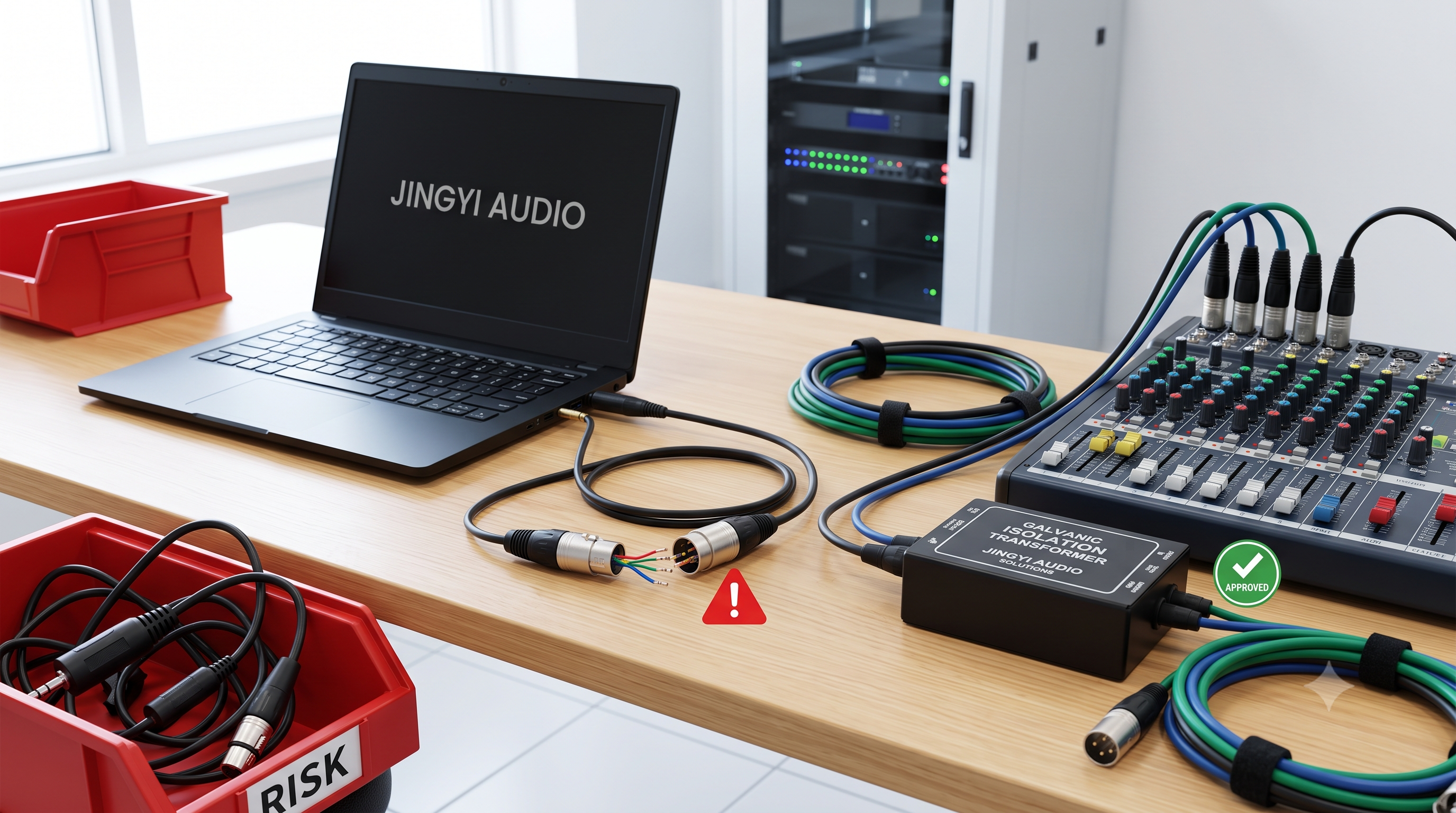
To fix ground loops cleanly, use a 1:1 line isolation transformer. A transformer passes sound signals magnetically while keeping input and output ground connections separated.
5. Answers to Common Field Questions (FAQ)
FAQ 1: Why does engaging a ground lift turn off condenser microphones?
Short Answer: Condenser mics need Pin 1 to return DC electricity to the power supply; lifting Pin 1 cuts this loop.
Detailed Breakdown: Phantom power needs a full loop to work. Power travels out on Pins 2 and 3 (+48V DC) and must travel back on Pin 1 (0V reference). When you turn on a ground-lift switch, you open the circuit on Pin 1. Kirchhoff's Current Law shows that breaking this path drops current to zero (
FAQ 2: Can you send +48V phantom power from two sound boards down one passive XLR Y-splitter?
Short Answer: Yes, it is electrically safe for both consoles and the microphone, though it reduces sound levels slightly.
Detailed Breakdown: Mixing console inputs place
Wiring two identical
This doubles the available max current (up to 20 mA) while keeping voltage at +48V DC. However, passive splits split the audio load, dropping overall signal level by 3 dB to 6 dB. For pro setups, use transformer splits or digital audio networks (like Dante or AES50).
FAQ 3: What causes ground loop hum in long XLR runs, and how does AES48 fix it?
Short Answer: Ground loops happen when voltage differences between wall outlets send noise current through cable shields; AES48 routes this current into the gear frame instead of audio circuits.
Detailed Breakdown: When audio devices connect to separate wall outlets, small potential differences (
The preamp amplifies this voltage drop as 60Hz hum. AES48 fixes this by connecting Pin 1 directly to the outer metal frame of the gear at the jack entry point. Noise bypasses internal circuit board traces and drains straight to earth ground.
FAQ 4: Can multi-channel audio snakes share one single ground shield wire?
Short Answer: No, sharing a common ground shield causes channel crosstalk, phantom power pops, and setup errors.
Detailed Breakdown: Budget cable snakes that connect all Pin 1 pins to one shared ground wire cause three major issues:
-
Phantom Power Crosstalk: Turning on phantom power on Channel 1 sends current down the shared ground, causing pops on adjacent channels.
-
Signal Bleed: High-level line signals (+4 dBu) leak into nearby low-level mic lines (-60 dBV) due to missing channel shielding.
-
Hard Troubleshooting: A single short circuit on a common ground breaks the whole cable snake.
Always specify multi-channel snakes with individually foil-shielded, insulated cable pairs.
FAQ 5: How do you adapt balanced XLR outputs to unbalanced RCA inputs correctly?
Short Answer: Wire Pin 2 to the RCA center tip, combine Pin 3 and Pin 1 to the RCA outer ring, and reduce line signal strength by ~12 dB.
Detailed Breakdown: Converting balanced XLR to unbalanced RCA drops noise cancellation and alters signal levels. Pro audio operates at
Without proper level attenuation pads, a
|
Conversion Type |
Cable Wiring Pinout |
Voltage Level Change |
Primary Risk |
Professional Fix |
|---|---|---|---|---|
|
XLR Out to RCA In |
Pin 2 → Tip Pin 3 + Pin 1 → Sleeve |
|
Overdrives input; heats output op-amp |
Use active converter or |
|
RCA Out to XLR In |
Center → Pin 2 Shell → Pin 1 + Pin 3 |
|
High background hiss |
Use active step-up preamp or DI box |
|
XLR Out to TRS In |
Pin 1 → Sleeve Pin 2 → Tip Pin 3 → Ring |
Unity Gain (0 dB shift, keeps balanced signal) |
TRS plug pulls out under vibration |
Use locking 1/4-inch TRS panel jacks |
6. Pro Audio Installation Rules
Follow these five rules when buying and setting up enterprise audio installations:
-
Require AES48 Compliance: Specify AES48 chassis grounding on all bid requests for mixers, DSPs, and active speakers.
-
Buy Separately Shielded Cable Snakes: Ensure every channel in multi-pair cables features its own individual foil shield and drain wire.
-
Use Line Isolation Transformers: Place 1:1 line isolation transformers between gear connected to different power distribution panels.
-
Follow Proper Powering Steps: Plug in all XLR cables before turning on +48V phantom power to protect delicate ribbon mics.
-
Use Active Matching Boxes: Avoid cheap passive adapter cables when connecting pro XLR outputs to home RCA gear.
7. Installation Checklist
-
[ ] Verify Pin 1 connects directly to the metal gear case on all jacks.
-
[ ] Check that phantom power supplies maintain
$+48\text{V DC} \pm 4\text{V}$ under load. -
[ ] Verify input load impedance (
$Z_{in}$ ) measures at least 5 times higher than output source impedance ($Z_{out}$ ). -
[ ] Confirm multi-channel audio snakes feature individual foil shields for every channel.
-
[ ] Install 1:1 isolation transformers on long audio runs between different electrical panels.