


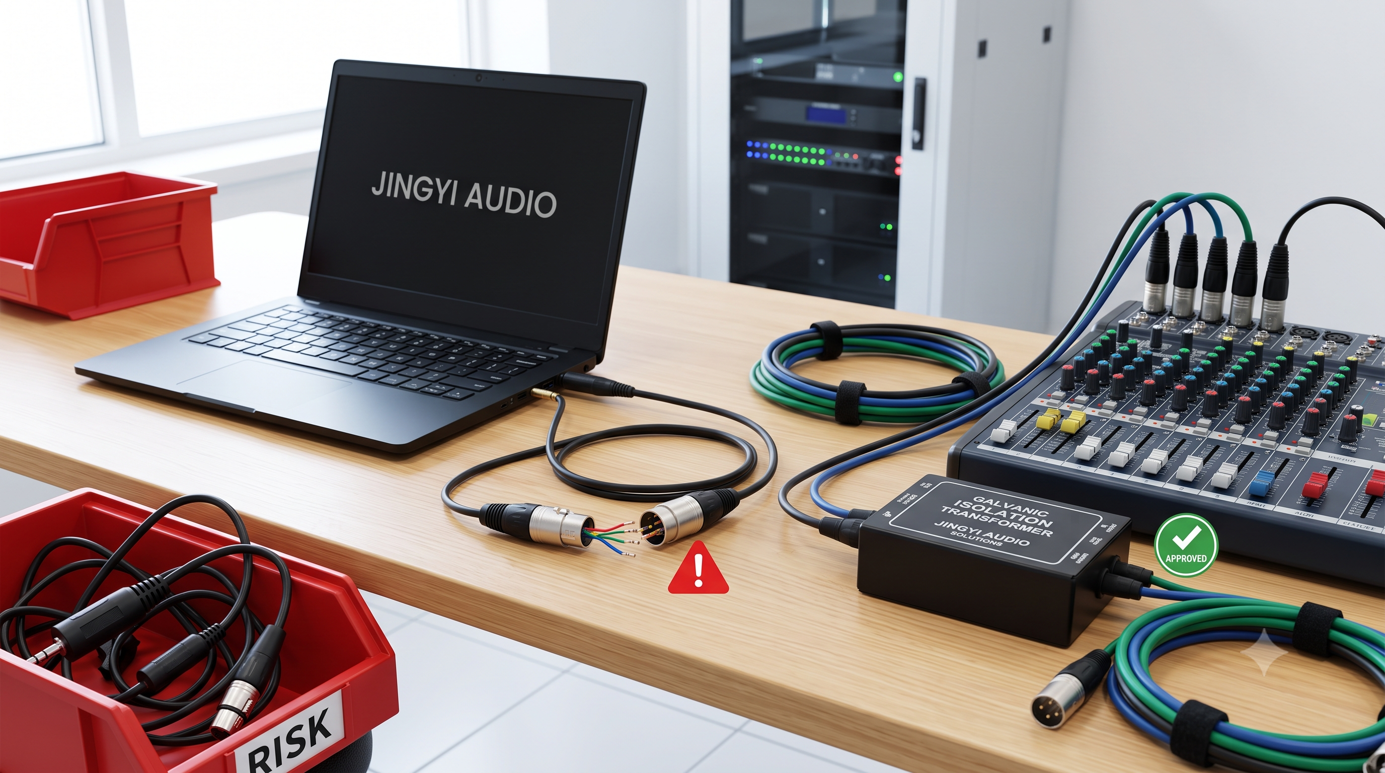

XLR Connector Pin Configuration: 3-Pin Standard, Y-Cable Risks, and OEM/ODM Guide
Author: Lynn Zhang, CEO at Jingyi Audio
Published: March 10, 2026
Last Updated: March 10, 2026
Reviewed by: Jingyi Audio Engineering Team
Audience: Audio cable OEM/ODM customers
Lynn Zhang is the CEO at Jingyi Audio and works with OEM/ODM buyers on custom audio cable projects, including XLR cable assemblies, connector pinout verification, shielding design, and production quality control for live sound, studio, and installed audio applications.
The standard XLR connector pin configuration for a 3-pin audio connector is simple: Pin 1 = shield/ground, Pin 2 = hot (+), and Pin 3 = cold (–). For audio cable OEM/ODM buyers, this is not just a wiring detail. It affects compatibility, noise control, polarity consistency, product reliability, and what happens after the shipment reaches the customer.
Quick Answer
If you only need the short version, here it is: the standard 3-pin XLR pinout is Pin 1 shield/ground, Pin 2 hot, Pin 3 cold. A passive XLR Y-cable should not be used to combine two outputs into one mic input, and a cable that passes continuity can still fail in real use if polarity or shield wiring is wrong.
What Is the Standard 3-Pin XLR Connector Pin Configuration?
The standard 3-pin XLR pinout is Pin 1 = shield/ground, Pin 2 = positive or hot, and Pin 3 = negative or cold. This is the standard most professional audio equipment follows today. The Neutrik XLR FAQ lists this as the normal 3-pole XLR wiring reference, and Shure’s XLR wiring guide confirms the same pin assignment for balanced audio connections.
3-pin XLR pin functions:
-
Pin 1: Shield / Ground
-
Pin 2: Hot / Positive
-
Pin 3: Cold / Negative
In a balanced audio line, Pins 2 and 3 carry opposite-polarity versions of the same signal. Shure’s explanation of balanced audio connections explains that the receiving input reads the difference between those two conductors. That helps reject noise picked up along the cable run, which is one reason XLR is still the standard choice for microphones, stage lines, and many line-level professional audio links.
For OEM/ODM buyers, this matters because a cable can look clean on the outside and still cause trouble later if the pin map is wrong, the shield is handled badly, or polarity changes from one batch to another.
Why correct pin assignment matters in production
Correct XLR pin assignment affects more than whether signal comes through. It also affects:
-
noise rejection
-
polarity matching between channels
-
phantom power routing
-
compatibility with mixers, stage boxes, interfaces, and powered speakers
-
product return rate
-
troubleshooting time after delivery
A cable is not really “correct” just because sound passes through it. It also needs to behave properly in an actual system.
XLR Pinout Terminology
Here are the core terms buyers and engineers usually mean when they talk about XLR wiring:
-
Pin 1: Shield / ground
-
Pin 2: Hot / positive
-
Pin 3: Cold / negative
-
Pin 2 hot: The current professional polarity convention
-
Balanced audio: Two signal conductors carrying opposite polarity to help reject noise
-
Polarity reversal: Pins 2 and 3 swapped
-
Pin 1 problem: Noise trouble caused by poor shield or chassis grounding design
Can XLR Y-Cables Be Used in Reverse to Combine Signals Into One Mic Input?
Short answer: No. A passive XLR Y-cable may be used to split one source in some cases, but it should not be used in reverse to combine two outputs into one mic input.
“I’ve seen a few XLR Y-cables for splitting a mic signal (all genders covered). I’m assuming that these can be used in reverse for combining signals to a single mic input. Is this possible?”
The practical answer is no. Two output stages should not simply be tied together. Rane’s technical note “Why Not Wye?” explains the reason clearly: when outputs are connected together with a passive Y connection, each output tries to drive the other. That can lead to level loss, distortion, unstable behavior, or odd loading conditions.
For audio cable OEM/ODM suppliers, this is not only a wiring issue. It is also a product-definition issue. If a cable is sold as an “XLR splitter,” some customers may assume it also works as a “combiner.” That mistake can turn into avoidable support requests, complaints, or returns.
What should be used instead?
If the job is to combine signals properly, the right tool is one of these:
-
a small mixer
-
an active summing circuit
-
a transformer-isolated combiner
-
a correctly designed resistive summing network for that use case
If you sell or private-label Y-cables, make the intended use plain on the product page, spec sheet, and packaging.
“DMX and XLR cables are being mixed up – will we have problems?”
Short answer: Sometimes, yes. They may appear to work in some setups, but they should not be treated as the same product in professional use.
“DMX and XLR cables are being mixed up – will we have problems?”
This happens a lot in live production because the connector shell can look the same at first glance. But similar connectors do not always mean the same electrical purpose or the same performance in the field. Audio cables are sometimes used for DMX in a pinch, and DMX cables sometimes pass analog audio. Still, “it worked once” is not the same thing as “this is the right cable for the job.”
For OEM/ODM buyers, the risk is bigger than signal quality alone. It can also cause:
-
inventory confusion
-
wrong product selection
-
slower troubleshooting on site
-
extra support pressure
-
blame placed on the cable supplier for a use-case mix-up
The easiest ways to reduce this are simple and practical:
-
print clear jacket markings
-
use different heat-shrink colors
-
keep separate SKUs for audio and lighting/data products
-
state the intended application clearly on the datasheet and product page
For B2B buyers, these small choices can prevent a lot of downstream noise.
“Can I plug a line level XLR into a mic (XLR)/line (TRS) combo input?”
Short answer: Sometimes, yes, but only if the input path and gain staging are correct. The connector may fit even when the signal level is still wrong.
“Can I plug a line level XLR into a mic (XLR)/line (TRS) combo input?”
This question comes up often because people mix up connector type and signal type. An XLR connector does not always mean mic level. Some XLR connections carry line level, and some gear uses impedance-balanced outputs instead of fully differential outputs. Shure’s note on impedance-balanced XLR outputs is a useful reference here because it shows that connector format and electrical behavior are not always the same thing.
A line-level XLR output connected to a mic preamp input can cause:
-
overload
-
distortion
-
harsh clipping
-
reduced headroom
-
confusion about whether the cable is faulty
For OEM/ODM customers, this matters when building:
-
XLR to TRS assemblies
-
XLR patch cables
-
adapter cables
-
stage-box breakout looms
-
interface and mixer accessory cables
A cable may be wired correctly and still be used in the wrong signal-level context. That is why technical drawings, product descriptions, and sales communication should clearly separate pin compatibility from signal-level compatibility.
“Can it cause any problems if the + and – pins get reversed for a mic or DI signal on its way to a mixer?”
Short answer: Yes. It usually will not damage the gear, but it can cause polarity inversion, weak mono summing, and thin or hollow sound when signals are combined.
“Can it cause any problems if the + and – pins get reversed for a mic or DI signal on its way to a mixer?”
If Pins 2 and 3 are reversed, the signal polarity flips. On a single isolated channel, the result may not sound obviously wrong. But in stereo pairs, dual-mic setups, or mono sums, that reversal can create:
-
partial cancellation
-
weak low-frequency response
-
poor image stability
-
thin combined sound
-
uneven tonal balance between channels
This is one of the most costly XLR mistakes in cable production because the cable still passes audio. A simple continuity test may say the cable is fine, while the customer hears a serious system problem later.
That is why OEM/ODM quality control should verify pin mapping and polarity, not just basic continuity.
Why Is Pin 2 Hot on an XLR Connector?
Short answer: Pin 2 hot is the modern professional standard, although some older equipment used Pin 3 hot.
Today, the normal expectation in professional audio is Pin 2 hot. That should be the default for nearly all modern audio cable production. Some older equipment was wired Pin 3 hot, and that older convention still comes up in vintage gear support, legacy system maintenance, and special custom requests.
For cable factories, the safe approach is simple: do not assume the word “standard” means the same thing to every buyer if the system includes older equipment. Any nonstandard pinout should be confirmed in writing on the drawing, sample approval, and production order.
A safe production note looks like this:
-
Standard configuration: Pin 1 shield, Pin 2 hot, Pin 3 cold
-
Nonstandard configuration: Only by written customer confirmation
That small step prevents expensive misunderstandings later.
Is Pin 1 the Same as Audio Ground?
Short answer: Pin 1 is the shield/ground connection in the XLR standard, but system grounding is more complex than simply calling it “audio ground.”
This matters because poor shield handling is a common cause of hum and buzz complaints. AES material on the well-known Pin 1 problem shows why weak grounding and bad shield termination can let interference enter the audio path.
For cable manufacturers, the practical lesson is not to oversimplify Pin 1. Inside the cable assembly, Pin 1 must be handled cleanly and consistently. In the complete system, the result also depends on how the connected equipment handles chassis and signal grounding.
Common Pin 1 risks in OEM/ODM production
Common production-related Pin 1 issues include:
-
weak or contaminated solder joints
-
inconsistent shield prep length
-
stray strands touching nearby terminals
-
poor strain relief causing shield failure over time
-
connector view confusion during manual assembly
These are small shop-floor details, but they often show up later as customer complaints about hum or unstable performance.
Can an XLR Output Carry Line-Level Instead of Mic-Level?
Short answer: Yes. XLR is a connector type, not a guaranteed signal level.
Many professional products use XLR connectors for line-level output, including mixers, processors, powered speakers, and wireless receiver outputs. Some are fully balanced, while others are impedance-balanced or set up for a certain gain structure.
For OEM/ODM buyers, this means product descriptions need to be specific. A request for a “standard XLR cable” is often not enough. Better wording includes:
-
microphone cable
-
line-level XLR interconnect
-
patch cable
-
AES/EBU digital cable
-
adapter cable
-
stage-use XLR loom
The clearer the intended use, the lower the risk of sourcing mistakes.
Are 3-Pin XLR Audio Cables the Same as DMX Cables?
Short answer: No, not as a best practice. They may look similar, but they should not be treated as the same product in professional use.
This is where product catalog structure matters. If your company offers both audio and lighting/data cables, keep them separate in site navigation, product families, and data sheets. That helps buyers understand what they are ordering, and it also helps search engines understand the difference between your product groups.
Useful internal links on a WordPress site could include:
If a buyer lands on this page through a technical search, those links help move them from general understanding to product selection and inquiry.
Common XLR Wiring Mistakes That Cause OEM/ODM Problems
1. Pins 2 and 3 swapped
This is one of the most common XLR production faults. The cable still passes signal, but polarity is wrong in the actual system.
2. Pin 1 terminated poorly
A weak shield connection can lead to hum, buzz, or unstable performance.
3. Front-view vs rear-view confusion
Operators sometimes mirror the pinout while soldering from the back of the connector.
4. Assuming all XLR ports are mic level
The connector shape does not define signal level.
5. Selling splitters without a clear use-case note
Users may try to combine outputs passively, then blame the cable when the result is distortion or weak audio.
Jingyi Audio Case Example
Short answer: In custom cable production, the most expensive defects are often not dead cables, but cables that pass signal while failing in real use.
At Jingyi Audio, a typical OEM troubleshooting case involved a customer evaluating a batch of custom 3-pin XLR patch cables for live sound rack integration. Initial bench testing showed continuity on all samples, but the customer reported thin summed audio and unstable low-frequency performance when two feeds were combined later at the mixer stage.
During the root-cause review, the issue was traced to a polarity inconsistency introduced during manual assembly. One production station had referenced the connector from the wrong solder-side orientation, which caused Pins 2 and 3 to be reversed on part of the batch. Because the cables still passed audio, the problem was not caught by a continuity-only inspection.
The corrective action included:
-
adding connector-specific rear-view work instructions
-
keeping an approved golden sample at the production line
-
requiring pin-map verification instead of continuity-only testing
-
recording outgoing inspection results for polarity mapping
This case shows a simple truth that applies to many OEM/ODM cable projects: the best QA system tests for the kinds of failures customers actually hear in the field, not only for whether current passes through the cable.
Expert Insight From Lynn Zhang
From an OEM/ODM point of view, many XLR cable problems are not obvious at first glance. A cable can look neat, pass continuity, and still cause a customer complaint later because of polarity reversal, poor shield termination, or unclear intended use.
In practical production work, the first three checks should always be:
-
Does Pin 1 go to Pin 1, Pin 2 to Pin 2, and Pin 3 to Pin 3?
-
Was the connector assembled from the correct rear solder view?
-
Is the cable being sold and used for the correct signal purpose?
These checks are simple, but they solve a surprising number of production and after-sales problems.
OEM/ODM Buyer Checklist for XLR Cable Projects
Before approving a custom XLR cable order, buyers should confirm these points:
-
the pinout standard or any custom pin assignment
-
connector gender on both ends
-
cable application, such as mic, line, patch, install, adapter, or data use
-
shielding method
-
whether phantom power may be present in the application
-
the factory test method
-
labeling and traceability requirements
Continuity alone is not enough. The test process should also verify polarity and correct pin mapping.
FAQ
What is the standard 3-pin XLR connector pin configuration?
Short answer: Pin 1 is shield/ground, Pin 2 is hot, and Pin 3 is cold.
This is the accepted standard for modern 3-pin XLR audio wiring. It is the reference point most professional audio equipment expects.
Can XLR Y-cables combine two outputs into one input?
Short answer: No. A passive Y-cable should not be used to combine two outputs.
If signals need to be combined, use a mixer, active summing stage, transformer-isolated combiner, or another circuit made for that job.
Can reversed XLR polarity damage equipment?
Short answer: Usually no, but it can create audio problems.
Pins 2 and 3 swapped usually will not damage gear, but the result can be weak mono summing, thin sound, and phase-related problems when channels are combined.
Is Pin 1 the same as audio ground?
Short answer: Pin 1 is the shield/ground connection, but full system grounding is more complex.
In the cable, Pin 1 is straightforward. In the full audio chain, grounding behavior also depends on the equipment design.
Can an XLR output be line level?
Short answer: Yes.
XLR is only the connector format. Some XLR connections are mic level, some are line level, and some are used for other signal types.
Are XLR and DMX cables the same?
Short answer: No, not as a best practice.
They may look alike, but they should be treated as separate products in professional use and product catalogs.
Key Takeaways
-
The standard XLR connector pin configuration is Pin 1 = shield/ground, Pin 2 = hot, Pin 3 = cold
-
Passive XLR Y-cables should not be used to combine two outputs
-
XLR connector type does not automatically define signal level
-
Pin 1 handling is a big factor in shielding and noise performance
-
Polarity errors can pass signal while still causing major real-world problems
-
OEM/ODM factories should verify pin mapping, polarity, and application fit, not continuity alone
Final Thoughts
For audio cable OEM/ODM buyers, understanding XLR connector pin configuration is not just a technical exercise. It is part of product quality, system compatibility, support efficiency, and long-term customer trust. When a factory builds to the correct pin standard, documents exceptions clearly, and tests each assembly against real application risks, it reduces returns and makes the product easier for distributors, installers, and end users to trust.