


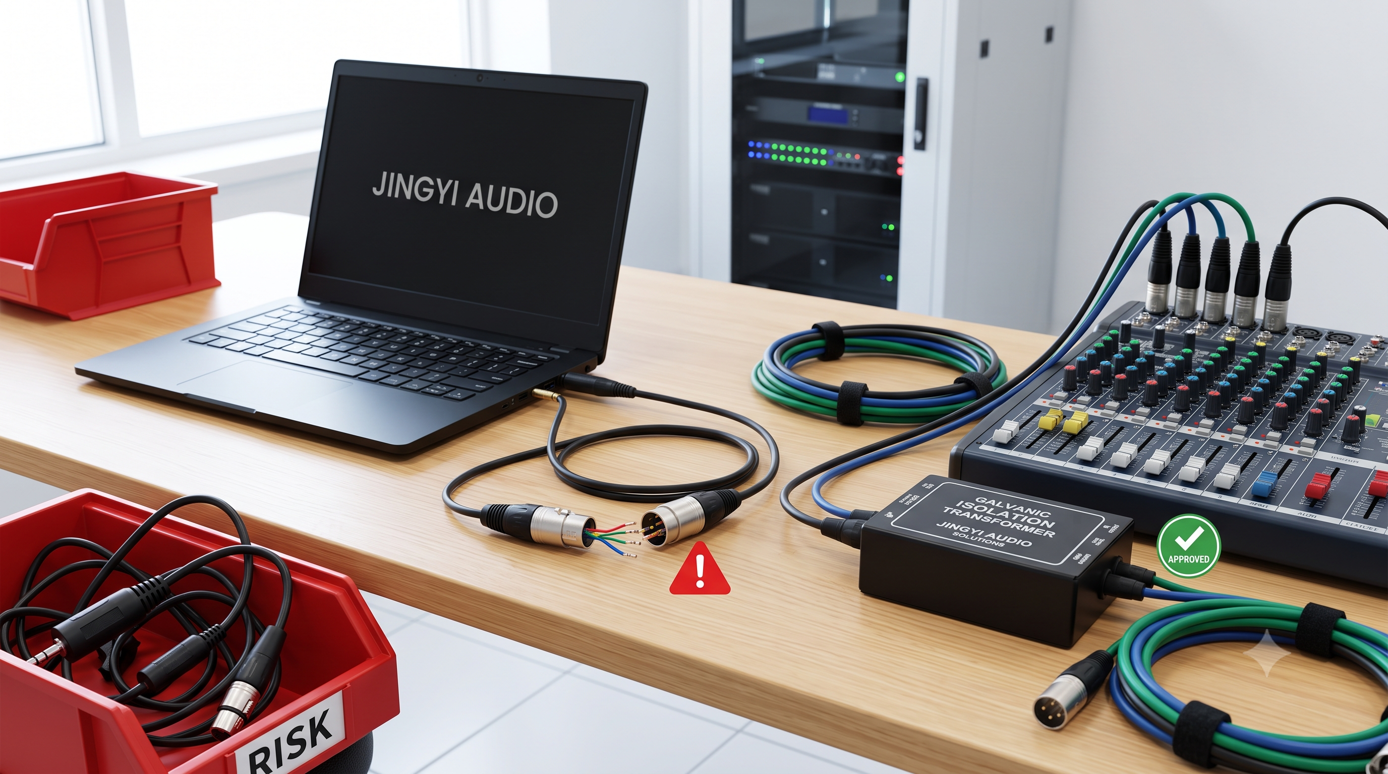


Car Audio Cable Management: B2B Engineering Guide
By Lynn Zhang (CEO at Jingyi Audio)
Published on July 17, 2026
1. Introduction: Modern Vehicle Integration
Modern vehicle wiring systems are more complex than ever. Clean wiring is not just about looks anymore. It keeps the system safe from major electrical failures and fires. Since modern cars run on complex computer networks, the space for electronics has shrunk. At the same time, the demand for high-current power and clean, noise-free signals has gone up.
Installers, custom shops, suppliers, and fleet managers must standardize how they handle car audio cable management. This is the only way to keep systems safe and working for a long time.
B2B Market Growth
This push for standardization comes alongside massive industry growth. The global market for trailer and specialized automotive control harnesses was valued at $4.8 billion in 2025. It is on track to reach $8.1 billion by 2034, growing at a compound annual growth rate (CAGR) of 5.9%.
This steady expansion is driven by the increasing complexity of cabin electronics in commercial transit conversions, active safety integrations, and specialized transport fleets. This rapid growth puts pressure on tier-one suppliers and aftermarket integration shops. They must standardize cable assemblies, cut out manual integration errors, and keep up with strict safety rules.
2. Industry Standards & Environmental Obstacles
A vehicle is a tough place for electronics. Unlike static devices in a home, a vehicle harness must withstand:
-
Continuous physical vibration and mechanical shock.
-
Intense heat cycles (ranging from hot engine bays to freezing winter temperatures).
-
Water, road salt, and dirt.
-
Engine oil, fuel, transmission fluid, and brake fluid.
To stop wires from shorting, melting, or catching fire, professional cable routing and harness design must follow established global standards.
Critical Industry Standards
-
ISO 6722: This standard specifies the size, heat limits, and electrical benchmarks for single-core low-voltage cables in road vehicles. It governs parameters like thin-wall insulation, voltage breakdown thresholds, and flame-retardant performance.
-
SAE J1128: The North American standard for primary low-voltage cables. It defines heat-resistance classes, which are essential for selecting cables that pass through the hot firewall from the engine bay to the cabin.
-
ISO 16750: This standard outlines thorough environmental testing methods for electrical equipment in vehicles. It tests how well components handle continuous vibration, high humidity, thermal shock, and salt spray. Following these rules ensures that custom audio harnesses do not rot away inside vehicle cavities.
Understanding and following these standards keeps your custom wiring safe for the life of the car.
3. Materials Science Behind High-Quality Cable Runs
Designing a great car audio cable management layout requires solid knowledge of metals, insulation plastics, and noise-damping materials.
Conductor Metallurgy: OFC vs. CCA vs. Tinned Copper
[Oxygen-Free Copper (OFC)]  --> Low Resistance, Highly Flexible, Long Life (Industry Gold Standard)
[Copper-Clad Aluminum (CCA)] --> Low Cost, High Resistance, Rust Risk (Needs Larger Wire Gauge)
[Tinned Copper]              --> Best Against Rust (Ideal for Damp & High-Humidity Zones)
-
Oxygen-Free Copper (OFC): The gold standard for power transmission and clean signal pathways. OFC has minimal electrical resistance and holds up great under mechanical stress. It prevents voltage drop over long runs without needing massive, bulky outer jackets.
-
Copper-Clad Aluminum (CCA): Often used in budget retail setups or simple fleet builds. While lighter and cheaper, B2B procurement managers must account for its high electrical resistance. CCA requires much larger wire diameters to handle the same current without overheating. In addition, its aluminum core corrodes quickly when exposed to moisture.
-
Tinned Copper: Standard copper strands coated in a micro-layer of tin. This is the mandatory specification for marine applications and vehicles working in damp environments. The tin barrier blocks oxidation, keeping the connection points clean and low-resistance.
Primary Insulation Chemistry: Engine Bay vs. Cabin Routing
Insulation materials must match the exact area where they are installed:
-
Cross-Linked Polyethylene (XLPE - TXL, GXL, SXL): Rated for heat up to 125°C. XLPE formulations handle oil, fuel, and intense heat extremely well. This makes them the standard choice under SAE J1128 for engine bay routing and heavy power runs.
-
Polyvinyl Chloride (PVC - FLRY-B, AVSS): These thin-walled, lightweight formulations are made for passenger cabins (like dashboards, center consoles, and side sills). FLRY-B (under ISO 6722) and AVSS (under JASO D611) reduce harness bulk, making them easy to run through tight wire channels.
Acoustic & Vibration Damping (Stopping BSR)
In premium audio setups, cable management also affects sound quality. Loose wires running behind door panels or dash assemblies rattle and shake. In the industry, this is known as Buzz, Squeak, and Rattle (BSR).
To stop BSR, professional installers wrap wire bundles in specialized Polyethylene Terephthalate (PET) fleece tape, such as Tesa 51608. This tape offers Class C noise damping and Class A/B abrasion resistance. It matches the look of OEM factory harnesses while protecting copper lines from sharp metal panel edges.
Material Specification Summary
|
Standard / Specification |
Material Class |
Thermal Limits (Continuous) |
Compliance Framework |
Primary Installation Zone |
Performance Capabilities |
|---|---|---|---|---|---|
|
SAE J1128 TXL |
XLPE |
-40°C to 125°C |
SAE, IATF 16949 |
Engine compartments & heavy power paths |
Exceptional resistance to oil, fuels, and high heat. |
|
ISO 6722 FLRY-B |
PVC |
-40°C to 105°C |
ISO, ECE R118 |
Dashboards, center consoles, and side run sills |
Ultra-thin profile optimized for tight spaces. |
|
JASO D611 AVSS |
PVC |
-40°C to 85°C |
JASO, JIS |
Low-voltage signal routing in vehicle interiors |
Highly flexible, strictly calibrated conductor resistance. |
|
Tesa 51608 |
PET Fleece Tape |
-40°C to 105°C |
ISO 554, OEM Standards |
Interior cabin wire bundling and panel interfaces |
Premium BSR damping, high flexibility, and hand-tearable. |
4. Modern Integration & OEM Compliance
Since modern vehicles rely heavily on digital networks (such as CAN-bus, LIN-bus, and MOST fiber optics), slicing into factory wires is a bad idea. Modern B2B integrations use modular systems that preserve factory wire harnesses to protect vehicle warranties and keep computer networks running smoothly.
                  MODERN MODULAR INTEGRATION WORKFLOW

   [OEM Head Unit Output] ---> [Vehicle-Specific T-Harness] ---> [DSP / Amp Input]
                                                                       |
   [Factory Speaker Lines] <--- [Amplified Return Loop]  <-----------+
Non-Destructive Routing Technologies
-
Vehicle-Specific T-Harness Adapters: T-Harnesses plug directly between the OEM head unit and the vehicle wiring harness. This lets installers split out audio signals, send them to aftermarket digital signal processors (DSPs) or amplifiers, and loop the amplified output back to the factory speaker locations—all without cutting a single factory wire.
-
Web-Programmable Interfaces: Hardware systems from Firstech or iDatalink connect directly with the vehicle's digital brain. Technicians can pre-program system behaviors, door chimes, steering wheel controls, and active noise cancellation (ANC) bypasses on a computer, cutting out the need for analog wire-tapping.
Real-World Custom Shop Case Studies
-
3D Printed Modular Clamps: Top-tier shops are moving away from standard nylon zip ties. They now use 3D-printed modular wire clamps. Sized exactly for heavy power lines (like 1/0, 4, or 8 AWG), these screwless, recessed-mounting clamps secure cable paths along amplifier racks. They prevent electromagnetic interference (EMI) by keeping a fixed physical separation between power cables and signal lines.
-
Double-Sided Carpeted Mounting Decks: For high-end fleet and consumer builds, technicians construct specialized mounting boards using 3/8-inch CDX plywood wrapped in matching vehicle carpet. By drilling clean pass-through holes next to the amplifier and DSP terminals, all power, ground, and speaker wires run on the back of the board. This completely hides the wiring, protects it from physical damage, and stops cabin vibration.
-
High-Efficiency 9-Conductor Speedwire: When routing signals from a dashboard stereo to trunk-mounted electronics, professionals use multi-conductor Speedwire (such as Stinger or EFX 18 AWG OFC). This single cable packs four stereo channels (eight color-coded wires) and a blue remote turn-on line inside a flexible PVC jacket. Running one Speedwire through vehicle side kick panels cuts installation times by over 60% compared to running nine individual wires.
-
Custom PCBA and Harness Sourcing: For large-scale fleet deployments, integrators partner with custom harness builders certified under ISO 9001 and IATF 16949 (such as ZEH or Wanshih). These suppliers manufacture pre-assembled, plug-and-play harnesses with integrated PCBA acoustic tuning, DSP signal routing, and IP67-rated waterproof connectors, shortening design and testing cycles by up to 30%.
5. FAQ: Technical Queries and Troubleshooting
Q1: Mechanical Crimping vs. Thermal Soldering: Which is Better in High-Vibration Environments?
Short Answer: Mechanical crimping is always better than soldering for primary automotive wiring. It creates a gas-tight, vibration-resistant connection that will not crack or fail under constant road movement.
The Engineering Science
Mechanical crimping is fully compliant with SAE/USCAR-21, IEC 60352-2, and IPC/WHMA-A-620 standards. Manual soldering is not allowed for main vehicle wire harnesses.
Under high pressure, a professional crimping tool subjects the wire strands and the terminal barrel to physical plastic deformation. This forces the individual copper strands to cold-flow, compressing them into a dense, interlocking honeycomb structure. This process shears away microscopic oxide layers on the wire surface and creates a gas-tight, oxygen-free cold weld.
Conversely, manual soldering introduces critical failure modes in vehicles:
-
Capillary Solder Wicking: Molten solder naturally wicks up the stranded copper wire underneath the insulation, transforming a flexible wire into a solid, rigid copper rod.
-
Stress Concentration: Under constant road vibration, physical stress concentrates right at the boundary where the flexible copper wire meets the rigid, soldered section. This leads to fatigue and snaps the wire strands.
-
Corrosion: Acidic flux residues from manual soldering, if not perfectly cleaned, accelerate internal copper oxidation, introducing unwanted electrical resistance.
-
Creep and Cold Flow: Pre-tinning a wire before inserting it into a crimp terminal is prohibited under IPC/WHMA-A-620. Solder is a soft metal; under the constant mechanical pressure of a crimp barrel, the solder will cold-flow and shift over time, loosening the connection and creating a hot, high-resistance spot.
Crimp vs. Solder Performance Matrix
|
Mechanical Property |
Mechanical Crimping (Gas-Tight Cold Weld) |
Manual Soldering (Thermal Solder Joint) |
|---|---|---|
|
Vibration Resistance |
Superior; maintains full wire flexibility right up to the crimp terminal interface. |
Poor; capillary wicking creates a rigid section highly vulnerable to vibrational fatigue. |
|
Mechanical Strength |
High; consistently retains over 90% of the wire's ultimate tensile strength. |
Variable; can weaken rapidly under mechanical load and thermal cycling. |
|
Consistency / Repeatability |
High; calibrated ratcheting tools ensure uniform compression every cycle. |
Low; highly dependent on operator skill, iron temperature, and flux cleaning. |
|
Chemical Stability |
High; gas-tight seal prevents internal oxidation and moisture ingress. |
Vulnerable; unneutralized acidic flux residues promote localized corrosion. |
|
Standard Compliance |
Compliant; satisfies SAE/USCAR-21, IEC 60352-2, and IPC/WHMA-A-620. |
Prohibited; restricted to internal PCBs and coaxial RF cables. |
Q2: Speedwire Efficiency: Can We Route High-Density Signals via Multi-Conductor 18 AWG Cables?
Short Answer: Yes, you can use 18 AWG Speedwire for standard setups running up to 75W RMS over 15 to 20 feet. Do not use it for high-power subwoofers, which need thicker, discrete 12 or 14 AWG lines.
The Technical Bottleneck
At 15 feet, the round-trip resistance of high-quality 18 AWG OFC Speedwire is low enough that signal insertion loss is negligible (well under
However, Speedwire must never be used for high-power, low-impedance configurations, such as high-output active mid-bass drivers or subwoofers running at 1
Standard Dash-to-Trunk Routing with 9-Conductor Speedwire
[OEM Head Unit / LOC] --(Single 18 AWG Speedwire: 4x Audio + Remote)-- [Trunk Amplifier / DSP]
Discrete High-Power Subwoofer Routing
[Trunk Amplifier] ===(Heavy Gauge 10/12 AWG OFC Discrete Cable)===> [Subwoofer Enclosure]
Q3: Why is My AGU Fuse Holder Melting if the Fuse Hasn't Blown?
Short Answer: It melts because weak spring clips and oxidation create localized electrical resistance, generating extreme heat. This localized heat melts the plastic housing without drawing enough total current to blow the fuse.
The Physics of Localized Thermal Runaway
AGU fuse holders rely on pressure from spring-loaded brass clips to secure the solid metal end caps of the glass fuse. Under continuous vibration and heat cycles, these clips gradually lose their grip. This weak contact, combined with microscopic surface oxidation, creates contact resistance (
Using Joule’s Law, we can calculate the power (
Where:
-
$P$ is the power dissipated as heat (Watts). -
$I$ is the continuous current through the circuit (Amperes). -
$R_{contact}$ is the contact resistance at the clip interface (Ohms).
If poor spring tension or oxidation introduces a minor resistance of just
A localized heat dissipation of
                      LOCALIZED THERMAL RUNAWAY

 [Spring Clip] ====== (Microscopic Oxidation & Weak Tension) ====== [Fuse Cap]
                                  |
                      Contact Resistance (R) = 0.05 Ω
                        Current Draw (I) = 40 A
                                  |
                      Continuous Heat (P) = 80 Watts!
                                  V
                    [Plastic Fuse Block Melts]
The Engineering Solution
To prevent thermal runaway, B2B procurement managers and system integrators must phase out AGU fuse blocks. Systems should exclusively deploy bolted-down fuse architectures, such as ANL, mini-ANL, or MIDI fuse blocks. These configurations clamp the power cable's ring terminals directly to the solid fuse element using heavy threaded studs and hex nuts, establishing a low-resistance, vibration-proof, gas-tight mechanical connection.
Q4: How Do I Safely Integrate Add-a-Circuit Fuse Taps in CAN-bus Vehicles?
Short Answer: Connect the fuse tap so the hot battery feed connects to the input terminal of the tap, and only use it on non-critical circuits with a 1A to 3A fuse. This keeps the new load isolated and prevents current from back-feeding through the factory fuse.
The Danger of Backwards Installation
An Add-a-Circuit fuse tap splits a single factory fuse slot into two isolated paths:
-
The bottom slot preserves the vehicle's original accessory circuit (OEM).
-
The top slot feeds the auxiliary wire for the new audio component (such as a DSP or amplifier turn-on trigger).
For the tap to function safely, you must orient it so that the "hot" battery feed of the fuse panel directly contacts the input line side of the fuse tap.
Correct Fuse Tap Orientation (Hot Feed on Terminal 1)
Line (Battery +12V) ---> [Terminal 1] ---> [Fuse Slot 1 (OEM)]  ---> [Terminal 2] ---> OEM Load
                                      ---> [Fuse Slot 2 (Aux)]  ---> [Pigtail Wire] ---> New Load (DSP Trigger)
In this correct layout, each circuit draws current independently from the main battery line.
Incorrect Fuse Tap Orientation (Hot Feed on Terminal 2 - Backwards)
Line (Battery +12V) ---> [Terminal 2] ---> [Fuse Slot 1 (OEM)] ---> [Terminal 1] ---> [Fuse Slot 2 (Aux)] ---> New Load
In this backward configuration, all auxiliary current is forced to pass through the factory OEM fuse first. If the aftermarket load draws significant current, it will blow the OEM fuse prematurely or cause a cascade heat failure inside the vehicle's fuse box.
CAN-bus Isolation
Modern vehicle Electronic Control Units (ECUs) continuously monitor resistance and current draw across factory circuits. To prevent throwing Diagnostic Trouble Codes (DTCs), fuse taps should only be placed in non-critical accessory slots (such as cigarette lighters) and use low-amperage fuses (1A to 3A).
For highly sensitive CAN-bus environments, the tap should not power any accessory directly; instead, it should be wired to trigger an isolation relay, drawing clean power directly from the battery to power the aftermarket equipment.
Q5: Can I Trim Cable Strands to Fit Large Power Wires Into Subwoofer Terminal Cups?
Short Answer: No, cutting back wire strands creates a tight bottleneck that causes dangerous heat buildup. Instead, crimp on a tinned-copper wire ferrule or a pin reducer to fit the terminal securely.
The High-Current Math
Consider a high-performance subwoofer system delivering
A current of nearly
If an installer trims away 50% of the copper strands at the terminal cup to squeeze the wire into a small spring terminal (reducing it to a 14 AWG equivalent), the local resistance at that connection spikes. The high current flowing through this bottleneck will generate intense heat, easily melting the plastic terminal cup, destroying the speaker voice coil, or triggering a short circuit.
Incorrect Strand Trimming (Bottleneck Risk)
[8 AWG Run (55A)] ===(Strands Trimmed Down to 14 AWG)===//===> [Standard Cup Terminal]
                                                               *High Localized Resistance & Heat!
Correct Compression Ferrule Integration
[8 AWG Run (55A)] ===[Crimp-On Tin-Plated Copper Pin Ferrule]=====> [Standard Cup Terminal]
                                                               *Preserves Full Cross-Sectional Area
The Engineering Solution
Rather than trimming the conductor, installers must crimp high-quality tinned-copper wire ferrules or compression pin-style gauge reducers onto the wire end. These tools compress the entire, uncut stranded wire bundle into a solid, highly conductive metal pin that fits securely into standard spring-loaded terminals, ensuring full cross-sectional current delivery.
6. Strategic Recommendations for B2B Procurement and Shop Standards
Based on field data, engineering standards, and modern vehicle architectures, B2B procurement managers and fleet operations should implement the following protocols to optimize installation workflow and eliminate warranty claims:
-
Standardize on Calibrated Crimp Terminations: Mandate the use of professional, ratcheting crimping tools calibrated to specific terminal families (such as Delphi or Deutsch). Completely prohibit manual soldering for primary power and harness assemblies to guarantee gas-tight, vibration-resistant terminations.
-
Transition Sourcing to 100% OFC Cabling: Phase out Copper-Clad Aluminum (CCA) cables across all high-reliability and high-power applications. Standardize sourcing on true-gauge Oxygen-Free Copper (OFC) and tinned-copper wires to prevent voltage drops, maximize power transmission, and eliminate galvanic corrosion risks.
-
Incorporate Web-Programmable T-Harness Systems: Deploy vehicle-specific T-harness kits and web-programmable software interfaces (Firstech/iDatalink) for all modern audio installations. This preserves the physical integrity of OEM wiring, ensures compliance with factory warranties, and cuts vehicle dashboard labor hours.
-
Deploy Bolted-Down Fusing Systems: Deprecate glass barrel (AGU) style fuse blocks from all inventory catalogs. Transition exclusively to bolted-down ANL, mini-ANL, or MIDI fusing blocks to eliminate mechanical spring-tension degradation and prevent localized thermal runaway.
-
Utilize Professional Wire Wrapping Materials: Specify PET fleece sound-damping tape (such as Tesa 51608) for all interior cabin wiring runs. This prevents Buzz, Squeak, and Rattle (BSR) phenomena, provides robust abrasion resistance, and replicates the premium look and feel of factory OEM harnesses.
-
Mandate Wire Ferrules and Gauge Reducers: Prohibit the trimming or shaving of copper wire strands at amplifier or speaker terminals. Mandate the use of tinned-copper wire ferrules and compression pin adapters to preserve conductor cross-sectional areas and ensure low-resistance, reliable connection points.
7. Next Steps
Modern vehicle electronics demand structured, highly engineered solutions. The era of loose, manual splicing and non-standardized routing is gone. By implementing systematic car audio cable management, using compliant primary insulation (like XLPE and thin-wall PVC), and standardizing on gas-tight mechanical crimping, vehicle integrators can guarantee unmatched system longevity, safety, and acoustic performance.
Implement These Standards in Your Shop Today
Protect your fleet investments, eliminate costly warranty callbacks, and deliver OEM-grade reliability on every build.
Are your shop's internal installation standards fully compliant with ISO 6722 and SAE/USCAR-21? Contact Jingyi Audio today to schedule a technical procurement audit and upgrade your team's wiring standards.