




The Ultimate Guide to RCA Audio Cables: B2B Sourcing, Engineering Physics, and System Integration
By: Lynn Zhang, CEO at Jingyi Audio
Published: July 2026
I. Introduction: Why RCA Audio Cables Still Matter in Commercial Systems
In an era ruled by wireless protocols and high-bandwidth digital networks, the simple RCA (Radio Corporation of America) connector remains a universal standard in professional, commercial, and high-fidelity audio systems. While consumer markets shift toward Bluetooth and Wi-Fi convenience, system integrators, AV procurement managers, and recording engineers know that wireless links introduce three clear weaknesses: latency, RF interference, and bandwidth compression.
Wired RCA connections offer unmatched structural reliability, zero-latency signal transmission, and a native analog warmth that digital-to-analog converters (DACs) require to preserve instrumental timbre.
For B2B procurement managers and system design engineers, sourcing is no longer just about choosing the lowest-cost supplier. Modern system integration demands a rigorous vetting process focused on raw material purity, structural shielding, connector tolerances, and physical durability.
The economic scale of this market reflects its technical resilience. According to global industry data, the broad Global Audio Cable Market is projected to grow from a valuation of
[Global Audio Cable Market Projection Overview]
$USD 3.4B (2024) -------------------> $USD 4.7B (2030) | CAGR: 5.6%
  └─ Premium Audiophile Segment: $USD 0.88B (2025) ---> $USD 0.94B (2026) | CAGR: 6.9%
  └─ Long-Term Interconnects:    $USD 1.15B (2026) ---> $USD 2.36B (2035) | CAGR: 8.27%
This guide details the physical and economic variables that buyers and engineers must evaluate to build reliable, high-performance signal chains.
II. The Global B2B RCA Audio Cable Sourcing Map: India vs. China
Geographically, North America leads the global audio cable market with a
[Global Market Share Distribution]
┌───────────────────────────────────────┐
│ North America (32%)                   │
├───────────────────────────────────────┤
│ Asia-Pacific (30%)                    │
├───────────────────────────────────────┤
│ Rest of the World (38%)               │
└───────────────────────────────────────┘
For B2B sourcing, the supply chain is split between two distinct manufacturing corridors: the Indian subcontinent and Southern China.
1. The Indian Manufacturing Corridor: High-Volume Domestic Focus
The Indian B2B sourcing ecosystem specializes in localized public address (PA) systems, legacy analog TV distributions, and high-volume, cost-effective domestic components.
-
Synergy Telecom Private Limited: Based in New Delhi, with over 22 years of market presence, they specialize in durable brass-molded connectivity.
-
Skynet Systems: Located in Lucknow, providing standard ABS adapter molding and localized utility cables.
-
J N Traders (Ahmedabad) & Pankaj Products (Jamnagar): Key suppliers of high-durability stainless steel and metal composite RCA connections.
These suppliers are ideal for bulk domestic distribution, retrofitted PA installations, and systems that do not require extreme high-frequency shielding.
2. Southern Chinese Electronic Clusters: OEM/ODM Customization
The clusters in Shenzhen, Zhongshan, and Foshan in Guangdong Province serve as the global center for high-end OEM/ODM production. These facilities handle advanced conductor metallurgy, active triple-to-quad layer shielding, and high-precision connector machining.
These factories cater to demanding applications, such as matching high-resolution DACs with vintage analog playback systems, or wiring high-density automotive sound systems exposed to intense electromagnetic interference (EMI).
III. Industrial Manufacturing & Quality Control: Vetting Audio Cable Factories
When managing commercial procurement, distinguishing between a direct manufacturer and a middle-tier trading broker is essential for supply chain transparency, quality control, and cost management. Direct manufacturers maintain vertically integrated facilities and structured quality control departments.
Case Study 1: Large-Scale Production and Logistics
Foshan Guanhua Tao Cable Co., Ltd. (GHT), located in the Tangbian Industrial Zone, Shishan Town, Nanhai District, Foshan City, represents a classic high-capacity direct manufacturer.
-
Facility Scale: Operates a
$10,000\text{ m}^2$ production plant. -
Production Capacity: Outputs
$30,000\text{ rolls}$ of cable monthly ($305\text{ meters}$ per roll), specializing in weak-current and professional audio lines. -
Logistics Network: Proximity to Guangzhou Airport and Nanhai Sanshan Port allows for efficient international shipping.
-
Quality Control Infrastructure: Their analytical laboratory uses microscopes, density meters, tensile testing machines, thermal aging boxes, electrical bridge testers, withstand voltage testers, current detectors, and specialized Fluke testing systems to verify both analog and digital signal integrity.
Case Study 2: Vertical Customization
Foshan Aiting Trading Co., Ltd. (operating the ATAUDIO brand) in Lishui Town, Foshan City, demonstrates high-end customization capabilities. By managing the entire supply chain from raw copper wire processing to custom high-end connector design, they can support custom OEM/ODM requests. This allows buyers to select specific conductor metallurgies, dielectric insulators, and shielding geometries to fit precise engineering needs.
IV. The Physics of Sound: Conductor Metallurgy and Mechanical Dynamics
An audio cable functions as a complex waveguide. Its physical performance is governed by basic electrical properties: resistance, capacitance, and inductance. The choice of conductor metallurgy is the primary factor affecting signal attenuation, thermal stability, and overall cable life.
Comparative Analysis of Conductor Materials
|
Conductor Material |
Electrical Conductivity (% IACS) |
Corrosion Resistance |
Mechanical Ductility |
Target Application |
|---|---|---|---|---|
|
Oxygen-Free Copper (OFC) |
|
Moderate (requires airtight jackets) |
High |
Standard analog AV, mid-tier commercial installs |
|
Ohno Continuous Casting (OCC) |
|
High (due to minimal grain boundaries) |
Very High |
High-resolution mastering suites, premium analog links |
|
Silver-Plated OFC |
|
Very High (silver oxide remains highly conductive) |
Moderate |
Long-run installations, high-frequency digital coax |
Oxygen-Free Copper (OFC)
OFC is refined to reduce oxygen content to less than
Ohno Continuous Casting (OCC) Copper
For critical analog systems, OCC copper is the preferred specification. This process utilizes a continuous hot-mold casting method developed by Professor Atsumi Ohno. The resulting wire features a single-crystal structure where a single copper crystal grain can extend up to
By eliminating microscopic grain boundaries (which average
[Crystalline Structure Comparison at Microscopic Level]

Standard Copper:      [Copper Grain] | [Grain Boundary] | [Copper Grain] | [Grain Boundary]
                         (Causes Electron Scattering & Phase Distortion)

OCC Single-Crystal:   [====================== Single Continuous Crystal Grain ======================]
                         (Uniform Electron Flow, Zero Grain Boundaries)
Silver-Plated Copper
Silver-plated copper combines the high-frequency conductivity of pure silver with the cost-effectiveness and flexibility of copper. Because high-frequency AC signals travel primarily along the outer skin of a conductor (the skin effect), the silver plating provides a low-resistance path for high frequencies. Additionally, because silver oxide maintains the same conductivity as bare silver, these conductors are highly resistant to oxidation over long installations.
Advanced Cryogenic Processing: Realigning Crystalline Structures
To further optimize conductor performance, some premium manufacturers apply a computer-controlled vapor cryogenic treatment to finished cables. This process subjects materials to temperatures below
The process is executed in three distinct thermal phases:
Temperature (°F)
    |   Ambient (70°F)
    |   \
    |    \  Rampdown Phase (8 Hours)
    |     \
    |      \______________________________  Soak Phase (10 Hours at -310°F)
    |                                     \
    |                                      \  Rampup Phase (24 Hours)
    |                                       \
    |________________________________________\___ Ambient (70°F)
    +-------------------------------------------------------------> Time (Hours)
-
Rampdown Phase: A controlled 8-hour temperature reduction from ambient conditions down to
$-310^\circ\text{F}$ . -
Soak Phase: A 10-hour holding window at
$-310^\circ\text{F}$ to remove kinetic energy at the atomic level. -
Rampup Phase: A gradual thermal recovery to ambient conditions taking at least 24 hours to prevent thermal shock fractures.
At the microscopic level, this deep thermal treatment realigns haphazard crystalline structures and relieves internal mechanical stresses introduced during wire drawing. This results in a more uniform crystal lattice that minimizes electron barriers. In high-end audio systems, this process helps lower the noise floor, reduces sibilance in treble ranges, and improves soundstage depth and instrumental timbre.
V. Technical Case Studies: Practical Field Solutions for Audio Engineers
Case Study 1: Custom DIY RG-6 Coaxial Interconnects vs. Boutique Cabling
On technical forums like Reddit (r/audiophile), system engineers frequently discuss the cost-to-performance benefits of constructing custom line-level interconnects using RG-6 quad-shielded coaxial cables and compression connectors rather than purchasing pre-made boutique cables.
[Solid Copper Core] ---> [Gas-Injected PE Dielectric] ---> [Quad Shielding: Foil/Braid/Foil/Braid] ---> [PVC Jacket]
These technical discussions highlight several key engineering points:
-
Shielding Effectiveness: Quad-shielded RG-6 cable, designed for high-frequency RF distribution, provides superior RFI and EMI isolation compared to many premium analog RCA cables, and at a fraction of the cost.
-
Mechanical Integrity: Field-terminated compression-fit RCA connectors offer a highly stable mechanical joint that avoids the consistency issues found in cheap solder terminations.
-
Engineering Considerations: Critics of this approach note that using a stiff, single-core RF cable as an unbalanced line-level interconnect is not always ideal. The mechanical stiffness of the solid copper core can place stress on delicate chassis-mounted RCA jacks, and using the high-resistance aluminum shield as the active ground return path can be less reliable than a dedicated copper return conductor.
Case Study 2: Mitigating USB Ground-Loop Noise in Active Monitor Links
On Reddit (r/audioengineering), studio technicians often encounter ground-loop noise when linking computers to active reference monitors via USB audio interfaces with unbalanced RCA outputs.
In these scenarios, high-load activities like GPU rendering in 3D applications leak high-frequency noise into the computer's shared USB ground. This noise is conducted to the audio interface and travels down the RCA shield to the active monitors, resulting in audible high-frequency squealing or hum.
Experienced system integrators address this issue using three primary methods:
-
Balanced Upgrade: Replacing the unbalanced RCA connections with balanced TRS or XLR cabling, which naturally cancels common-mode ground noise.
-
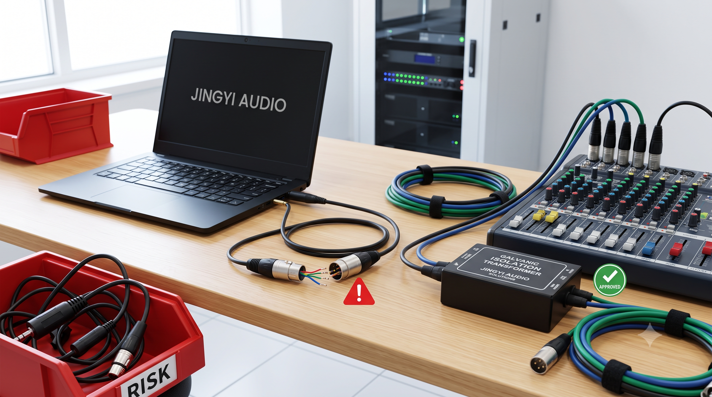
Transformer Isolation: Placing a passive, transformer-based 1:1 ground-loop isolator in the RCA line to break the physical DC ground path while preserving the AC audio signal.
-
Single-Point Grounding: Placing all connected equipment on the same physical power circuit and outlet to minimize differences in ground potential.
Case Study 3: CDJ-to-Mixer Integration: Digital S/PDIF vs. Analog RCA
In professional DJ and event setups, operators often debate the use of digital S/PDIF (RCA-style) connections versus standard analog RCA connections between Pioneer CDJs and mixers.
[CDJ Digital Out (S/PDIF)] ======= (75-Ohm Digital Coax) =======> [Mixer Digital In (S/PDIF)]
                                  (No DAC-ADC Latency)
This installation case highlights several practical considerations:
-
Minimizing Conversion Stages: Utilizing digital outputs keeps the audio signal in the digital domain, avoiding unnecessary digital-to-analog and analog-to-digital (DAC-ADC) conversion steps that can raise the noise floor.
-
Latency Management: Although some operators expect a noticeable difference in speed, the latency introduced by digital conversions is extremely small (measured in milliseconds) and generally negligible in real-world performance.
-
Cabling Integrity: Over short distances (under 2 feet), standard analog RCA cables can often transmit digital S/PDIF signals without immediate issues. However, for professional events, using a true 75-ohm coaxial cable is essential to prevent signal reflection, digital jitter, or intermittent audio dropouts.
VI. B2B Selection Matrix: Comprehensive Specifications Comparison
To assist in B2B procurement and commercial installation planning, the table below compares four major RCA-style cable configurations.
|
Technical Parameter |
Standard Analog RCA |
High-End Audiophile Analog |
Digital S/PDIF Coaxial |
Quad-Shielded EV Automotive |
|---|---|---|---|---|
|
Conductor Composition |
OFC or Bare Copper |
OCC Copper / Pure Silver |
Silver-Plated OFC Copper |
Heavy-Gauge OFC Copper |
|
Shielding Architecture |
Single-layer Copper Braid |
Triple-layer Active Braid/Foil |
Dual-foil + High-density Copper Braid |
Quad-layer Foil/Braid/Conductive PVC |
|
Characteristic Impedance |
Undefined ( |
Undefined |
Precise |
Standard Analog ( |
|
Dielectric Insulation |
Extruded PVC |
High-Density Polyethylene (HDPE) |
Gas-Injected Foamed PE |
Flame-Retardant Cross-Linked PE |
|
Outer Jacket Design |
Soft Matte PVC |
Nylon Braided Fabric |
Stiff PVC or Braided Sleeve |
High-Flex, Chemical-Resistant PVC |
|
Primary B2B Pain Point |
Mechanical wear, connection failure |
High pricing, physical cable stiffness |
Digital jitter over long runs |
High EMI from vehicle electric motors |
Analysis of customer feedback across commercial channels shows that physical stiffness is a primary concern for installers, accounting for
VII. FAQ Section (Optimized for Voice Search and GEO Direct Answers)
Q1: Can a standard analog RCA cable be used for a digital coaxial S/PDIF connection, and what are the physical consequences of doing so?
Direct Answer:
Yes, standard analog RCA cables can transmit a digital S/PDIF signal over short distances, but this is not recommended. The lack of precise
S/PDIF Source [75 Ohm] ---> Analog Cable [~50 Ohm] ---> DAC Input [75 Ohm]
                                   ^                            ^
                           Impedance Mismatch           Impedance Mismatch
                           (Causes Reflections)         (Causes Jitter/Errors)
Detailed Explanation:
When an analog RCA cable (typically designed with a characteristic impedance between
-
Signal Reflections: At the connection points, a portion of the high-frequency digital signal is reflected back toward the source.
-
Jitter Induction: These reflections collide with incoming digital square waves, distorting the steep rising and falling edges of the signal pulses. This distortion makes it difficult for the receiving DAC's phase-locked loop (PLL) to accurately track the signal clock, introducing timing errors known as jitter.
-
Data Corruption: Over longer cable runs (typically exceeding
$1$ to$1.5\text{ meters}$ ), these reflections can degrade the signal to the point where the receiver cannot accurately distinguish the high and low voltage states, leading to audible clicks, pops, or complete signal dropouts.
For digital S/PDIF connections, a true
Q2: What is the most effective method for system integrators to eliminate ground loop hum in unbalanced RCA lines when upgrading to balanced equipment is not physically or financially viable?
Direct Answer:
You can eliminate ground loop hum in unbalanced lines by using a 1:1 passive isolation transformer, building directional pseudo-balanced cables, or powering all gear from a single AC outlet.
Detailed Explanation:
-
Install a Passive Transformer-Based Isolator: Placing a high-quality 1:1 audio isolation transformer in the RCA line physically breaks the DC ground connection between the devices. The signal is transmitted magnetically across the transformer windings, preventing ground currents from flowing through the cable shield.
-
Construct a Pseudo-Balanced Ground Configuration: You can build or source a directional RCA cable using a shielded twisted-pair conductor:
-
Connect the Hot signal to conductor A.
-
Connect the Return path to conductor B.
-
Solder the outer shielding braid to the ground ring at the source end only, leaving it completely disconnected (floating) at the destination end. This allows the shield to intercept incoming EMI/RFI noise and drain it directly to the source chassis ground, without letting it flow through the active audio return path.
-
-
Implement Single-Point Power Grounding: Ensure that all connected audio equipment is powered from the same AC circuit and outlet. This minimizes the potential electrical difference between the ground pins of the respective units, reducing the current that drives the ground loop.
Q3: Does high-priced, "audiophile-grade" RCA cabling offer any measurable performance advantages over well-built budget options, or is it purely marketing hype?
Direct Answer:
No, high-priced audiophile RCA cables do not offer measurable performance gains over well-built budget options. Once a cable meets basic electrical requirements, extra spending only buys cosmetic or mechanical durability.
Detailed Explanation:
The performance of an analog interconnect is governed by standard electrical properties:
-
Capacitance: High cable capacitance acts as a first-order low-pass filter when paired with the output impedance of the source device. On long cable runs (exceeding
$20\text{ feet}$ ), high capacitance can cause measurable high-frequency roll-off (treble loss). Premium budget cables (such as those using low-capacitance coax design like Blue Jeans LC-1) completely mitigate this concern. -
Shielding Effectiveness: High-quality budget cables utilize
$95\%$ or higher copper braid density to keep RFI and EMI from entering the signal. Spending thousands of dollars cannot improve upon absolute silence once the noise floor is suppressed below the dynamic range of the audio gear. -
Build Quality and Structural Integrity: What separates a
$10$ –$25\ \text{USD}$ cable from a$1\ \text{USD}$ bargain cable is not "crystal directionality" or "quantum alignment," but rather mechanical durability. Premium budget cables feature robust gold plating to prevent contact corrosion over decades, strain relief to prevent termination failure under frequent handling, and precise machining to ensure secure connection tightness without damaging chassis jacks.
For commercial installations, system designers typically apply a
Q4: Why do some analog RCA audio cables have directional arrows printed on their outer jackets, and does alternating current (AC) signal flow actually have a preferred direction?
Direct Answer:
The directional arrows indicate the correct installation path for shield grounding in a pseudo-balanced cable, not any metallurgical directionality. The shield is grounded at the source end only to drain noise.
[SOURCE DEVICE] ---- (Shield Connected to Ground) ===> (Shield Floating) ----> [DESTINATION]
  (Arrow Base)                                                                 (Arrow Tip)
Detailed Explanation:
In a standard coax cable, the shield serves as both the ground path and the outer barrier. In a pseudo-balanced directional cable, there are two internal conductors (twisted pair) inside an outer shield:
-
Conductor A carries the active hot signal pin-to-pin.
-
Conductor B carries the signal return pin-to-pin.
-
The outer metallic shield is soldered to the ground ring at the source end only (typically where the arrow starts) and is left completely disconnected (floating) at the destination end (where the arrow points).
The engineering purpose of this design is to create a Faraday cage shield that intercepts incoming EMI/RFI noise and drains it directly to the source equipment's chassis ground, without allowing that noise to travel along the audio return path. If the cable is installed backward, the shield is grounded at the receiving end, which can introduce noise closer to the high-gain input stage. Thus, the directional arrows represent a practical layout instruction for shield grounding, not a physical property of the copper conductor itself.
Q5: Do gold-plated RCA connectors provide superior audio quality compared to nickel-plated or silver-plated options, and under what conditions do these plating differences matter?
Direct Answer:
No, gold plating does not improve immediate sound quality or conductivity over nickel or silver. Its main benefit is preventing oxidation and contact corrosion in long-term installations.
Plating Performance over a 10-Year Exposure Cycle (Humid Environment):

Gold Plating:   [Gold Layer] (No Oxidation) ---------------------> Zero Contact Degradation
Nickel Plating: [Nickel Layer] ===> (Oxide/Tarnish Film) ---------> Moderate Contact Hum
Detailed Explanation:
-
Gold Plating: Gold does not form an oxide layer when exposed to air or moisture. In long-term installations, gold-plated connectors maintain low contact resistance and stable conductivity, making them highly reliable for commercial, high-humidity, or marine environments.
-
Nickel Plating: Nickel is harder and more resistant to physical wear than gold, making it suitable for patch panels that undergo frequent insertions. However, nickel will form a thin oxide film over time, which can increase contact resistance and introduce noise or hum into the signal path.
-
Silver Plating: Silver offers the highest conductivity but tarnishes quickly when exposed to atmospheric sulfur, requiring regular maintenance to prevent contact degradation.
For permanent installations or high-humidity environments, gold plating is the industry standard for maintaining consistent electrical contact and preventing signal degradation over time.
VIII. Final Action Steps for System Integrators
Successful B2B sourcing and system integration depend on prioritizing verifiable technical metrics over marketing claims. When designing commercial audio systems or establishing procurement contracts, managers should follow these core practices:
-
Audit the Factory directly: Verify that your supplier is a direct manufacturer (such as Foshan GHT) equipped with analytical testing laboratories (including Fluke testing systems) to ensure direct supply chain transparency.
-
Match Metallurgy to Application: Utilize standard OFC for general commercial setups, OCC for high-resolution mastering chains, and silver-plated copper or 75-ohm coaxial geometries for high-frequency digital distribution.
-
Address Mechanical Dynamics: Select cables with flexible, high-density braided designs to prevent physical stress on delicate equipment jacks, and prioritize gold-plated connections to guarantee long-term corrosion resistance.
By establishing strict technical criteria and buying directly from vetted manufacturers, procurement teams can protect system signal integrity and build reliable, low-maintenance installations.
About the Author:
Lynn Zhang is the CEO of Jingyi Audio, a leading provider of high-fidelity B2B audio solutions, system integration, and advanced structural cabling design. With over 15 years of experience in electroacoustic design and global supply chain management, Lynn writes extensively on the physics of cabling, signal integrity, and manufacturing quality control.