


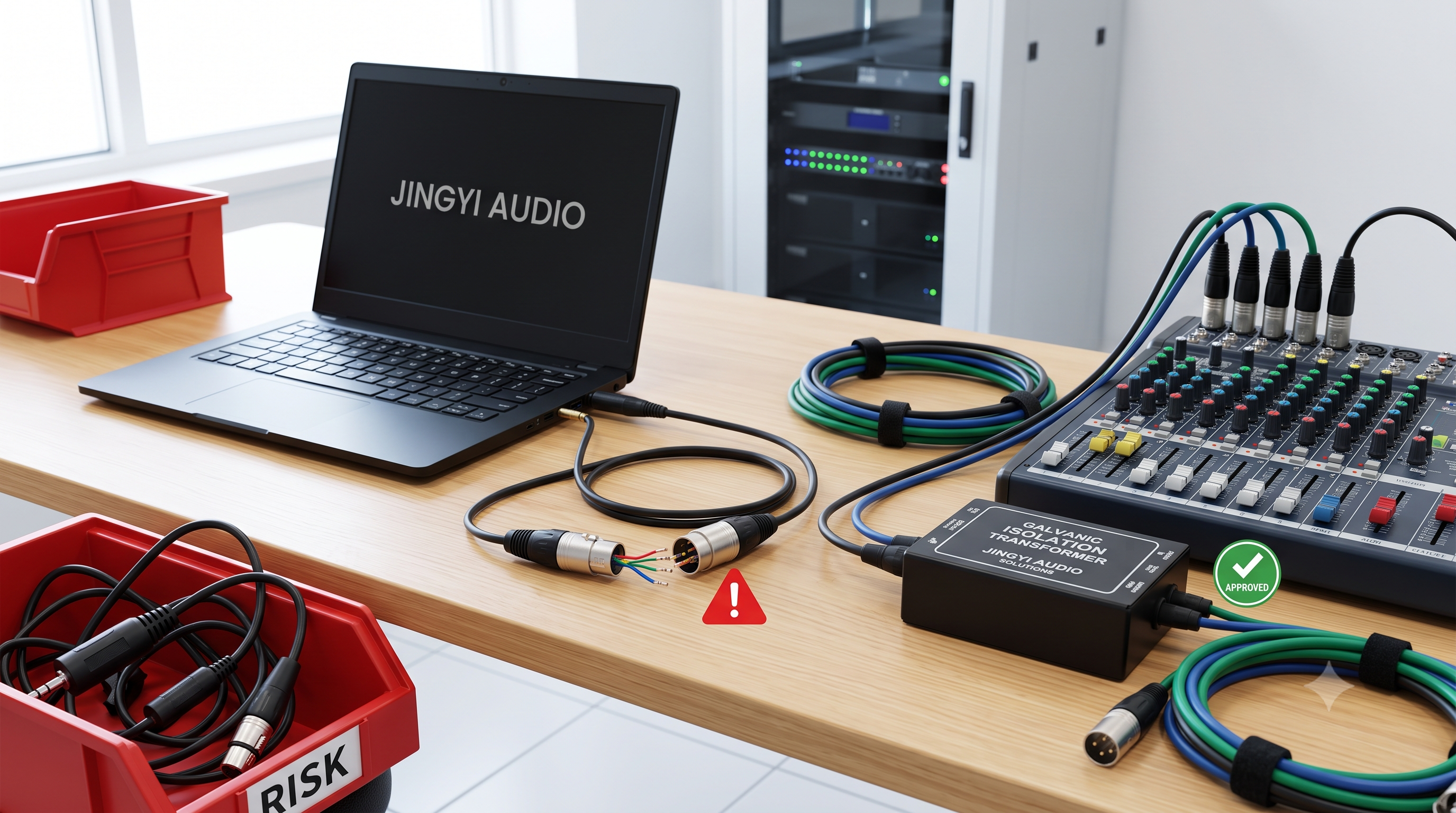


Professional Audio Cables: The Strategic B2B Technical and Procurement Bible
Is your commercial AV infrastructure vulnerable to silent, high-stakes failures? A single failing cable can shut down an entire multi-million dollar corporate boardroom or major live broadcast, triggering devastating downtime and expensive emergency service calls. Selecting the cheapest physical components is a short-sighted trap. This definitive guide reveals the deep physical metallurgy, safety certifications, and digital network parameters required to future-proof your enterprise installations.
1. Introduction: The Revolution in Enterprise AV Infrastructure
1.1 The Paradox of Consumer Wireless and Mission-Critical Physical Infrastructure
In consumer electronics, wireless audio is dominant. True Wireless Stereo (TWS) platforms and Bluetooth-enabled peripherals account for roughly
However, professional and commercial environments present a starkly different structural reality. In enterprise boardrooms, broadcast studios, sports arenas, and live performance venues, wireless transmission is treated as an operational risk. A single drop in wireless connectivity or a momentary RF packet collision during a live broadcast or executive board meeting can carry severe financial and reputational consequences.
For these mission-critical paths, robust, high-performance balanced signal transmission over physical cable infrastructures remains the mandatory industry standard.
[VISUAL PLACEHOLDER: Global Pro Audio Cable Market Expansion Infographic (2025-2035)
- Line chart showcasing market growth from $441.7M (2025) to $586.46M (2035) at a 3.2% CAGR.
- Callout map showing regional distribution: APAC (34%), North America (31%).
- Bullet metrics showing North American professional installations representing 45% of total regional market share.]
The global professional audio cable market is currently valued at approximately $441.7 million. Fueled by continuous corporate office builds, stadium modernizations, and broadcast studio upgrades, it is projected to expand to $586.46 million by 2035, growing at a compound annual growth rate (CAGR) of
Regionally, demand is led by the Asia-Pacific (APAC) region at
Because of heavy physical use in high-impact commercial venues, standard analog and digital cables have an average operational lifespan of only
1.2 Enterprise Sourcing Paradigms: Shifting from Unit Cost (FOB) to Total Cost of Ownership (TCO)
Talk to any enterprise AV technology director today, and they will tell you that the days of chasing the lowest Free-on-Board (FOB) unit cost are long gone. Modern B2B procurement operates under a rigorous Total Cost of Ownership (TCO) framework.
The purchase price of a cable represents only a fraction of its true cost over time. When a cable fails inside a wall cavity or under a raised floor, the economic impact includes:
-
System Downtime: Lost productivity during key corporate meetings or costly delays in commercial broadcast schedules.
-
Maintenance Labor: The high cost of deploying specialized technicians to trace, diagnose, and re-pull failed lines.
-
Premature Capital Expenses: Repeatedly buying cheap materials that fail rapidly under wear and tear.
Procurement pathways have evolved to reflect this TCO shift. While transactional B2B e-commerce platforms manage roughly
These offline agreements facilitate custom pinout engineering, hands-on physical evaluations, and long-term service-level agreements (SLAs) with global distributors. Major distributors, such as Intronics, offer specialized product and accessory portfolios through exclusive commercial brands like Eminent and Ewent to support large-scale enterprise rollouts.
2. Core Physics: Balanced vs. Unbalanced Signals
2.1 The Physics of Noise Rejection: Common-Mode Rejection Ratio (CMRR)
To specify the right cabling infrastructure, procurement teams must understand the core physics of noise rejection.
Unbalanced audio circuits utilize two conductors: a single hot signal wire and a shared shield/ground wire. Because any electromagnetic interference (EMI) or radio frequency interference (RFI) picked up along the cable run is added directly to the hot signal, unbalanced lines cannot reject noise. This limits unbalanced runs (such as standard instrument cables and RCA lines) to a maximum recommended length of
[VISUAL PLACEHOLDER: Vector Diagram of Balanced Signal Noise Cancellation (CMRR)
- Detailed circuit schematic illustrating how a source transmitter splits a mono signal into identical in-phase (Hot) and out-of-phase (Cold) signals.
- Diagram of external electromagnetic noise waves penetrating both conductors symmetrically.
- Illustration of the differential amplifier subtracting the Cold phase from the Hot phase: V_Output = V_Hot - V_Cold.
- Visual display showing the symmetrical noise peaks flattening to zero while the signal amplitude doubles.]
In contrast, balanced audio circuits utilize three conductors: a Hot (+) wire carrying the in-phase signal, a Cold (-) wire carrying an identical signal inverted by
When electromagnetic noise penetrates the cable, it affects both internal conductors equally (known as common-mode noise). At the receiving end, the differential amplifier executes a simple, yet powerful subtraction to reconstruct the clean audio signal:
Because the noise on both lines is identical, this subtraction cancels out the common-mode noise entirely while doubling the amplitude of the original audio signal.
The capability of a system to perform this noise rejection is measured as its Common-Mode Rejection Ratio (CMRR). High-quality balanced cables allow signals to travel hundreds of feet through high-interference environments with zero noise pickup.
2.2 Core Audio Connector Quick Reference
Selecting the correct connectors is vital for maintaining signal integrity, safety, and physical reliability in commercial installations. Below is a professional B2B reference guide for the primary connector types used in enterprise AV:
|
Connector Type |
Common Name |
Balanced / Unbalanced |
Typical Application |
Pinout/Structure |
|---|---|---|---|---|
|
XLR (3-Pin) |
"Cannon" Connector |
Balanced |
Professional microphones, active loudspeakers, digital AES/EBU connections |
Pin 1: Shield/Ground Pin 2: Hot (+) Pin 3: Cold (-) |
|
TS (1/4" or 1/8") |
Mono Jack |
Unbalanced |
Electric guitars, passive instrument DI boxes, legacy line-level inputs |
Tip: Hot (+) Sleeve: Shield/Ground |
|
TRS (1/4" or 1/8") |
Stereo/Balanced Jack |
Balanced (or Stereo) |
Balanced patch-bay runs, studio monitors, stereo headphone feeds |
Tip: Hot (L) Ring: Cold (R) Sleeve: Shield/Ground |
|
RCA |
Phono Connector |
Unbalanced |
Legacy commercial media players, consumer AV bridge devices, subwoofers |
Center Pin: Hot (+) Outer Ring: Shield/Ground |
|
SpeakOn |
Twist-Lock Speaker |
High-Current Power |
Passive high-power loudspeakers, professional power amplifiers |
Twist-lock safety housing, 2-pole or 4-pole high-current contacts |
3. Metallurgy and Physical Cable Construction
3.1 Oxygen-Free Copper (OFC) vs. Copper-Clad Aluminum (CCA): Resistivity and Power Loss Calculations
The electrical efficiency and durability of an analog cable are directly determined by the metallurgy of its internal conductors. B2B procurement agents often face intense pressure to purchase budget-friendly Copper-Clad Aluminum (CCA) cables instead of premium Oxygen-Free Copper (OFC) options.
We can mathematically expose this trap by revisiting classical electrical engineering. Under Ohm's Law:
the voltage drop (
where
The resistivity of pure Oxygen-Free Copper (OFC) is extremely low:
In contrast, aluminum has a significantly higher resistivity, meaning Copper-Clad Aluminum (CCA) exhibits an increased resistivity profile:
[VISUAL PLACEHOLDER: Microscopic Metallurgy and Resistivity Comparison Chart
- Cross-sectional illustration showing the solid, uniform grain boundaries of pure Oxygen-Free Copper (OFC).
- Cross-sectional illustration showing Copper-Clad Aluminum (CCA) with its aluminum core and thin outer copper plating.
- Sided bar chart illustrating the 1.5x higher electrical resistivity of CCA compared to OFC, alongside associated signal attenuation metrics.]
In physical power-loss tests, a standard 20-foot run of pure OFC cable loses only about
3.2 Mechanical Fatigue, Galvanic Corrosion, and Fire Risks
Beyond electrical losses, CCA cables present severe physical and mechanical vulnerabilities in commercial installations:
-
Mechanical Fatigue & Brittleness: Aluminum has poor tensile strength and flexibility. Repeatedly pulling, bending, or routing cables through tight conference table access boxes causes micro-fractures in the aluminum core of a CCA conductor. This leads to crackling audio, intermittent signal loss, and physical failure.
-
Galvanic Corrosion: When CCA conductors are terminated into brass or gold-plated connectors in humid environments, the contact of dissimilar metals triggers galvanic corrosion. This reaction forms a resistive aluminum oxide layer that acts as an electrical insulator, ruining the audio signal.
-
Elevated Fire Hazard: During continuous high-wattage power sweeps (such as in 100V line distributed speaker systems or high-output subwoofer runs), CCA conductors have been physically measured to run
$30^\circ\text{F} \text{ to } 50^\circ\text{F}$ ($16.7^\circ\text{C} \text{ to } 27.8^\circ\text{C}$ ) hotter than their pure copper counterparts, violating in-wall fire codes and introducing fire risks inside wall cavities.
|
Performance Parameter |
Oxygen-Free Copper (OFC) |
Copper-Clad Aluminum (CCA) |
Procurement Consequence |
|---|---|---|---|
|
Material Composition |
|
Aluminum core with Copper skin |
CCA compromises long-term reliability |
|
Electrical Resistivity ( |
|
|
CCA increases signal attenuation by |
|
Signal Power Loss (20-ft run) |
|
|
CCA strains amplifiers and degrades signal |
|
Mechanical Durability |
High flexibility, high tensile strength |
Highly brittle, prone to micro-fractures |
CCA is prone to physical breakages |
|
Corrosion Resistance |
High |
Low (susceptible to galvanic corrosion) |
CCA degrades rapidly in humid environments |
|
Thermal Fire Safety |
Standard operating temperature |
Runs |
CCA violates in-wall fire codes under high load |
3.3 Shielding Configurations: Foil, Braid, and Dual Shielding
To preserve signal integrity in high-interference environments, selecting the correct cable shielding is critical. B2B buyers must match the shielding configuration to the target installation path:
-
Foil Shielding (Aluminum Mylar + Drain Wire): Provides
$100\%$ physical coverage, making it highly effective at blocking high-frequency RFI (such as Wi-Fi, Bluetooth, and cellular signals). Foil is thin, lightweight, and easy to run through conduits. However, it is physically fragile and can tear under repeated bending. For permanent in-wall pathways, bulk plenum-rated CMP cables with foil shielding offer the optimal balance of fire safety, cost-efficiency, and protection. -
Braided Shielding (Woven Copper Grid): Consists of a woven mesh of copper wires. It provides physical durability and low-frequency EMI/ground-loop rejection. Because of its woven construction, tiny gaps exist in the grid, limiting physical coverage to
$70\% \text{ to } 95\%$ . Braided cables are thicker, heavier, more expensive, and require skilled labor to solder and terminate, making them ideal for high-impact touring-grade portable audio cables. -
Dual Shielding (Foil + Braid): The gold standard for commercial AV projects. By layering aluminum Mylar foil beneath a woven copper braid, engineers combine the
$100\%$ high-frequency RFI protection of foil with the physical strength and low-frequency ground-loop protection of a braid.
4. Building Codes and Fire-Safety Regulations: CMP, CMR, and CM
4.1 HVAC Plenum, Vertical Riser, and General Spaces
Sourcing cables for in-wall or vertical vertical pathways requires strict compliance with fire-safety and building codes. The National Electrical Code (NEC, Article 800) and the National Fire Protection Association (NFPA) categorize communications cables based on their flame resistance and smoke emission properties.
[VISUAL PLACEHOLDER: NEC / NFPA Fire Safety Certification and Substitution Hierarchy Flowchart
- Clean corporate infographic illustrating the unidirectional downward substitution pathways (CMP -> CMR -> CM).
- Clear warning callout emphasizing that the local Authority Having Jurisdiction (AHJ) has the ultimate power to halt projects if fire-safety markings are missing or uncertified.]
-
CMP (Communications Multipurpose Plenum): Plenum spaces are environments that circulate environmental air throughout a building, such as the open space above drop ceilings and below raised floors used for HVAC return air. These spaces are vulnerable to fire spread because constant airflow provides oxygen and can quickly distribute toxic smoke. CMP-rated cables are mandatory for plenum installations. To achieve CMP certification, cables must pass the rigorous NFPA 262 / UL 910 Steiner Tunnel flame test, which measures flame propagation and optical smoke density. CMP jackets are typically made from fluorinated ethylene polymer (FEP) or specialized low-smoke PVC, which restrict flame spread to under 1.5 meters, emit minimal toxic smoke, and self-extinguish.
-
CMR (Communications Multipurpose Riser): Riser spaces are vertical pathways, conduits, or elevator shafts that span across multiple floors. Because fire can travel quickly upward through vertical shafts, riser cables must resist vertical flame spread. CMR cables must pass the UL 1666 vertical flame test. Their jackets are usually constructed from heavy, flame-retardant PVC. While CMR cables prevent vertical fire spread, they do not meet the low-smoke generation standards required for plenum areas and are strictly prohibited in air-handling spaces.
-
CM (Communications General Purpose): CM cables are rated for general-purpose, same-floor applications. They utilize standard PVC jackets that meet the basic UL 1581 flame test. CM cables are suitable for exposed patch cables, desktop paths, and residential runs where local building codes do not require plenum or riser ratings.
4.2 Code Substitution Rules and B2B Sourcing Economics
To simplify inventory management and ensure compliance, procurement teams can utilize the hierarchy defined by building codes:
CMP (Plenum) cables feature the highest safety rating and can substitute for both CMR (Riser) and CM (General Purpose) cables in any installation. CMR cables can substitute for CM cables but cannot be used in plenum spaces. CM cables cannot replace CMR or CMP cables under any circumstances.
CRITICAL COMPLIANCE NOTICE: Under strict local building ordinances, the local Authority Having Jurisdiction (AHJ) holds final discretionary authority over code compliance. Even if a cable jacket is physically stamped "CMP," inspectors routinely audit safety documentation. Enterprise B2B procurement protocols must mandate that suppliers provide fully traceable UL Listed File Numbers alongside physical certificate copies. Failing to install verified cable ratings risks costly electrical audit failures, structural teardown orders, voided commercial property insurance policies, and severe life-safety liability.
|
Cable Jacket Rating |
Fire Safety Standard |
Flame Test Method |
Permitted Installation Spaces |
Sourcing Cost Ratio |
Substitution Eligibility |
|---|---|---|---|---|---|
|
CMP (Plenum) |
NFPA 90A, NFPA 262 |
UL 910 Steiner Tunnel |
Plenum air voids, HVAC ducts, drop ceilings, risers, walls |
High (approx. |
Can replace CMR and CM |
|
CMR (Riser) |
NEC Article 800 |
UL 1666 Vertical Burn |
Vertical shafts, vertical conduits, inter-floor paths (No Plenum) |
Moderate (approx. |
Can replace CM; cannot replace CMP |
|
CM (General) |
UL 1581 |
UL 1581 Horizontal Burn |
Exposed patch cords, desktop pathways, residential single-floor runs |
Low (approx. |
Cannot replace CMR or CMP |
5. Sourcing for Digital Audio Networks (AoIP)
5.1 Dante vs. AES67 Protocols
The commercial AV industry is replacing traditional multi-pair analog cables with digital Audio over IP (AoIP) protocols. These network systems reduce total cable volume, enable software-based routing, and prevent analog signal degradation over long runs.
Audinate's Dante is the leading proprietary digital audio networking protocol, used in over
AES67 is an open interoperability standard published by the Audio Engineering Society (AES). Rather than acting as a competing network ecosystem, AES67 acts as an open "translator" protocol, allowing equipment from different proprietary AoIP ecosystems—such as Dante, Ravenna, Q-LAN, and Livewire—to exchange audio streams.
|
Architectural Feature |
Dante (Audinate Ecosystem) |
AES67 (Open Standard) |
|---|---|---|
|
Protocol Type |
Proprietary |
Open Interoperability Standard |
|
Market Share |
|
Niche/Specialist (Broadcasting, Open tenders) |
|
Audio Transport Layer |
UDP/IP (Layer 3) |
RTP/UDP (Layer 3) |
|
Synchronization Method |
IEEE 1588-2002 (PTPv1) / PTPv2 |
IEEE 1588-2008 (PTPv2) |
|
Discovery and Routing |
Automatic via Dante Controller software |
Manual (via SDP/SAP or third-party NMOS) |
|
Switch Requirements |
Gigabit Managed (or Unmanaged in small scales) |
Strictly Managed, QoS, IGMP Snooping |
|
Typical Latency |
Configurable down to |
Typically |
5.2 The Invisible Killer: Energy Efficient Ethernet (EEE / IEEE 802.3az)
A common technical issue in modern AoIP integrations is the "invisible" packet sync error. While Dante manages its network synchronization automatically, activating AES67 mode requires a designated Precision Time Protocol Version 2 (PTPv2/IEEE 1588-2008) Grandmaster Clock.
Standard unmanaged switches with Energy Efficient Ethernet (EEE, also known as Green Ethernet or IEEE 802.3az) enabled can disrupt this clock synchronization. EEE dynamically puts switch ports into low-power sleep modes during brief periods of silence.
As documented in the Shure Dante Clocking Knowledge Base, these sleep cycles delay time-critical PTP sync packets, causing packet loss, clock drift, and audible dropouts.
[VISUAL PLACEHOLDER: Dante Controller Software UI Screenshot
- Focus on the Clock Status Diagnostic Panel.
- Showing a clear yellow warning exclamation triangle icon beside a device under "Sync Status."
- Callout text linking this specific error to asymmetric switch latency caused by active IEEE 802.3az (EEE) Green Ethernet sleep-cycle delays.]
For reliable AoIP performance, enterprise networks must utilize managed hardware optimized via our AoIP network switch configuration guide with EEE disabled. These switches should be configured with Quality of Service (QoS) prioritizing clock and audio packets, alongside Internet Group Management Protocol (IGMP) snooping to manage multicast flows.
5.3 Ethernet and Fiber Physical Sourcing (Cat5e to Cat7, and Beyond)
To support gigabit AoIP signals, network cabling must be specified correctly. Audinate's Dante cable recommendations outline standard guidelines for physical layer media:
-
Cat5e / Cat6: Ideal for general installations; they fully support gigabit speeds with low latency over standard commercial distances up to 100 meters.
-
Cat6a / Cat7: Engineered with shielded Cat6a and Cat7 Ethernet cables (often featuring individual foil-shielded pairs inside an overall braided shield). These standards provide high headroom and RFI/EMI protection, making them ideal for high-interference paths, long runs, or bundles where crosstalk is a risk.
-
Fiber Optic Cabling: For cable runs exceeding the 100-meter threshold of copper Ethernet, single-mode or multi-mode fiber optic cabling is required. Fiber completely eliminates electromagnetic interference, electrical ground loops, and signal degradation over long distances.
6. Digital vs. Analog Isolation: AES/EBU (110 $\Omega$ ) vs. Analog XLR
6.1 Characteristic Impedance and Signal Reflection Waveforms
A common field error in commercial AV procurement is treating analog XLR cables and digital AES/EBU (AES3) XLR cables as interchangeable. While they share the same physical 3-pin connector and identical pinout schemes, their electrical characteristics are fundamentally different.
[VISUAL PLACEHOLDER: Oscilloscope Waveform Comparison (Eye Diagrams)
- Waveform A (Correct 110-Ohm AES/EBU Cable): Showing a crisp, wide-open "Eye Diagram" with sharp digital transition edges, ensuring perfect bit decoding.
- Waveform B (Incorrect 75-Ohm or Analog XLR Cable): Showing a collapsing "Eye Diagram" rounded off by high capacitance and distorted by severe high-frequency signal reflections (standing waves) at the boundary mismatches.]
-
Characteristic Impedance: Analog XLR vs. digital AES3 cables have different characteristic impedance profiles. Standard broadcast-quality analog XLR cable typically has a characteristic impedance of
$45\,\Omega \text{ to } 100\,\Omega$ . In contrast, the AES/EBU digital audio standard strictly demands a cable with a controlled characteristic impedance of$110\,\Omega \pm 20\%$ . -
Bandwidth & Attenuation: Analog audio signals operate in the low-frequency audio band (
$\le 20\,\text{kHz}$ ). Digital AES/EBU carries high-frequency digital bitstreams extending into tens of megahertz (MHz). -
Signal Reflection and Waveform Distortion: If an analog cable with a lower characteristic impedance is introduced into a digital AES/EBU pathway, the impedance mismatch creates high-frequency signal reflections within the cable. This reflected energy causes inter-symbol interference and waveform distortion. The resulting high jitter levels lead to digital synchronization issues, audio dropouts, and complete loss of the digital feed.
Conversely, using a
7. Operational Best Practices and Case Studies
7.1 LinkedIn's "Last Meter Rule"
To maintain signal integrity across large-scale corporate deployments, enterprise AV designers and workspace technology managers have established a standardized design guideline known as the "Last Meter Rule".
-
The Principle: This practice dictates that all physical analog unbalanced connections—including 1/8-inch (3.5 mm) auxiliary inputs and RCA cables—must be kept shorter than a maximum length of 3 meters (10 feet).
-
The Technical Rationale: Unbalanced analog audio cables lack common-mode noise rejection, making them vulnerable to electromagnetic noise from nearby power lines, laptop chargers, and cellular networks. If a signal must travel across a larger distance (such as from a central conference room table to a display mounted on the far wall), the signal should be immediately converted near the source and routed digitally over shielded network lines (such as Dante, AES67, or HDBaseT). This rule has significantly reduced troubleshooting labor and system downtime in modern corporate environments.
-
High-Power Interference Mitigation: When routing lines under the "Last Meter Rule," field installers must keep unbalanced cables physically separated from laptop power cables—especially modern high-wattage Gallium Nitride (GaN) fast chargers. High-frequency switching transients from these power adapters can easily bypass standard unbalanced shielding, introducing high-frequency noise and interference into the analog signal path.
7.2 The "Dummy Plug" Muting Workaround
In a case study documented in professional integration channels, an AV installer encountered a firmware bug across a large batch of corporate commercial displays:
-
The Technical Challenge: Even when programmed to route audio to an external line-array system, the displays continued to play duplicate audio through their tiny, built-in internal speakers.
-
The Practical Solution: Rather than waiting for a manufacturer firmware update, the field engineer cut the plugs off several low-cost 3.5 mm auxiliary cables and sealed the raw exposed copper ends with heat-shrink tubing. Inserting these custom-made "dummy plugs" into the physical headphone/audio output jacks of the displays tricked the internal sensing circuits into disabling the internal speakers. This solution allowed the integration team to deliver the project on schedule.
-
Mass Enterprise Deployment Adaptation: A similar deployment method was used by an IT team configuring over 100 corporate laptops in an open floor layout adjacent to executive offices. To prevent loud, unmutable startup chimes from disrupting the office during initial system configuration, technicians inserted 3.5 mm dummy plugs into each laptop's physical jack prior to powering them on. This safely diverted the startup audio, maintaining a quiet work environment.
7.3 Multi-Core Looming and Storage Workflows in Large-Scale Environments
At high-pressure live events, such as major music festivals, efficiency during system strike and breakdown is critical. Industry professionals utilize specialized cabling workflows to meet tight logistics schedules:
-
Looming Strategy: Technicians group multiple signal lines (such as XLR, network Ethercon, and AC power lines) together into single, consolidated cable bundles or "looms". This minimizes tangles and ensures uniform pathways on stage.
-
Trunk Packing: At the conclusion of an event, the loomed cable bundles are wound and stored directly into designated, heavy-duty road trunks. Each trunk is clearly labeled by stage position or department. Assigning crews to manage specific sections of the stage prevents confusion, reduces labor time, and helps protect expensive cabling from physical damage during transit.
-
Troubleshooting Diagnostics: To ensure these custom looms remain functional, technicians perform digital multimeter diagnostic testing to measure pin-to-pin continuity and resistance, catching solder joint cracks or micro-fractures before the next deployment.
8. Key Takeaways
::: Key Sourcing & Engineering Takeaways
-
Transition to TCO: Evaluate cabling procurement based on Total Cost of Ownership (TCO), accounting for system downtime, replacement labor, and long-term durability rather than upfront unit cost.
-
Enforce Pure OFC Standards: Reject cheap Copper-Clad Aluminum (CCA) for analog lines to prevent high voltage drops, mechanical fatigue, galvanic corrosion, and fire risks.
-
Rigid Fire-Safety Compliance: Match building safety codes exactly using the substitution rule (
$\text{CMP} \implies \text{CMR} \implies \text{CM}$ ). Always request verified UL certification trace numbers to satisfy local Authority Having Jurisdiction (AHJ) building audits. -
Isolate AES/EBU Paths: Never substitute analog XLR cables for digital
$110\,\Omega$ AES/EBU runs; doing so introduces impedance mismatches and clock jitter. -
Disable Switch EEE: Always disable Energy Efficient Ethernet (EEE/IEEE 802.3az) on managed switches to protect PTPv2 clock synchronization in digital AoIP (Dante/AES67) environments.
-
Maintain the "Last Meter Rule": Limit unbalanced analog connections to 3 meters (10 feet) to prevent EMI/RFI noise in corporate spaces, keeping signal lines physically isolated from high-wattage GaN chargers. :::
9. Frequently Asked Questions (FAQ)
Q1: Why does a stereo 1/8" TRS to balanced XLR adapter cable make vocals sound thin or hollow?
This issue is caused by phase cancellation at the balanced input. A balanced XLR input is a differential receiver designed to reject common-mode noise. It expects a mono signal split into two identical polarities: the non-inverted "Hot" signal on Pin 2 and the inverted "Cold" signal on Pin 3. The differential amplifier on the receiving end subtracts the cold signal from the hot signal to reconstruct the audio:
When a stereo 1/8-inch TRS cable is adapted directly to a mono balanced XLR connector, the left stereo channel is routed to Pin 2 (Hot) and the right stereo channel is routed to Pin 3 (Cold). The differential amplifier then subtracts the right channel from the left:
In professional recordings, lead vocals, bass, and kick drums are mixed dead-center, meaning they are identical in both the left and right channels (
Q2: Can Bluetooth be trusted for mission-critical professional audio applications?
No. Industry professionals uniformly agree that Bluetooth is unsuitable for mission-critical professional audio for several key reasons:
-
High Latency: Standard consumer Bluetooth codecs (such as SBC, AAC, and standard LE Audio) introduce latencies of
$100\,\text{ms} \text{ to } 250\,\text{ms}$ . This far exceeds the maximum$15\,\text{ms}$ threshold required for live sound, stage monitoring, or video conferencing to prevent visible lip-sync issues. -
RF Overcrowding: Bluetooth operates in the unlicensed 2.4 GHz ISM band, which is shared with hundreds of consumer smartphones, guest Wi-Fi networks, and local wireless routers. This overcrowding leads to packet collisions and connection dropouts.
-
RF Absorption ("Saltwater Bags"): The human body is composed primarily of saltwater, which absorbs 2.4 GHz radio frequencies. A Bluetooth connection that works perfectly in an empty venue will often fail completely once the space is filled with an audience.
Q3: What is the primary difference between CMP, CMR, and CM cable ratings?
These ratings define the fire-resistance and smoke-emission characteristics of communications cables:
-
CMP (Plenum Rated): Mandatory for air-handling spaces, drop ceilings, and HVAC ducts. CMP cables pass the rigorous NFPA 262/UL 910 Steiner Tunnel test, emit very low smoke, and self-extinguish.
-
CMR (Riser Rated): Designed for vertical shafts or conduits spanning multiple floors. CMR cables pass the UL 1666 vertical flame test to prevent fire from traveling between floors, but they emit heavy smoke and are strictly prohibited in plenum areas.
-
CM (General Purpose): Suitable for general-purpose, same-floor, or residential installations. CM cables pass the basic UL 1581 flame test and are not rated for riser or plenum pathways.
Q4: Can I substitute a standard analog XLR cable for a digital AES/EBU run?
For very short runs under 10 meters, an analog cable may transmit the digital signal without issue. However, for longer professional runs, standard analog XLR cables will fail.
The primary cause of failure is an impedance mismatch combined with high cable capacitance. AES/EBU digital audio requires a controlled characteristic impedance of
This mismatch creates high-frequency signal reflections within the cable, rounding off the sharp transitions of the digital square wave and introducing time-domain jitter. This jitter makes it difficult for the receiving DAC to decode the digital clock, leading to digital sync errors and complete loss of the audio feed.
Q5: Why is Energy Efficient Ethernet (EEE) a major issue in Dante and AES67 networks?
Energy Efficient Ethernet (EEE/IEEE 802.3az) is designed to reduce power consumption on network switches by putting idle ports into low-power sleep modes during brief silences.
However, in digital audio networks (AoIP), Dante and AES67 rely on the Precision Time Protocol (PTPv1 or PTPv2) to synchronize the clocks of all connected devices. EEE sleep cycles delay these time-critical sync packets by micro-seconds. This delay disrupts clock synchronization, causing packet loss, audible clicks, pops, and sudden audio dropouts.
Q6: What type of network cable is recommended for Dante and AES67 installations?
For the majority of standard gigabit Dante runs up to 100 meters, Audinate recommends using Cat5e or Cat6 cabling.
For high-interference environments, long cable runs, or bundles where crosstalk is a concern, Cat6a or Cat7 cabling (which features individual foil-shielded pairs inside an overall braided shield) is recommended to provide higher headroom and RFI/EMI protection.
For runs exceeding the 100-meter threshold of copper Ethernet, single-mode or multi-mode fiber optic cabling must be used.
Q7: What are Carbon Nanotube (CNT) audio cables and are they commercially viable?
Carbon Nanotube (CNT) audio cables represent an environmentally sustainable advancement in cable manufacturing. Spin-off entities such as TRIMTABS Ltd., supported by the Swansea University nanotechnology research program, have successfully demonstrated proof-of-concept electrical and audio transmission wires constructed from recycled plastic waste.
While they offer electrical and mechanical performance comparable to commercial copper standards and significantly reduce carbon footprints, CNT cabling is currently in the specialized, high-end procurement stage and is not yet a mainstream replacement for standard copper lines.
Q8: How can a digital multimeter help troubleshoot phase issues in custom-soldered balanced cables?
Field technicians use a digital multimeter configured for continuity and resistance testing to verify that Pin 1 (Shield), Pin 2 (Hot), and Pin 3 (Cold) map perfectly on both ends of a balanced XLR or TRS cable.
If Pin 2 and Pin 3 are reversed on one end of the cable (a cross-wiring error), the signal phase is inverted by
Q9: Why is Copper-Clad Aluminum (CCA) illegal or prohibited for in-wall commercial installations?
CCA cables violate building safety codes for in-wall installations because aluminum has a significantly higher electrical resistance than pure copper. Under continuous high currents or high thermal loads (such as passive speaker lines), this increased resistance causes the cable to generate excess heat, running
Additionally, aluminum is highly brittle and prone to micro-fractures when pulled through tight wall conduits, which can lead to open electrical arcs inside the wall.
Q10: What is the "Last Meter Rule" and why is it used in corporate AV design?
The "Last Meter Rule" is an enterprise design guideline which dictates that all physical analog unbalanced connections (such as 1/8-inch auxiliary inputs or RCA lines) must be kept shorter than a maximum length of 3 meters (10 feet).
Because unbalanced cables lack common-mode noise rejection, they easily pick up electromagnetic interference from nearby power lines, laptop chargers, and cellular networks. Keeping these runs under 3 meters minimizes noise pickup, and any longer distances are immediately converted to balanced or digital signals near the source.