


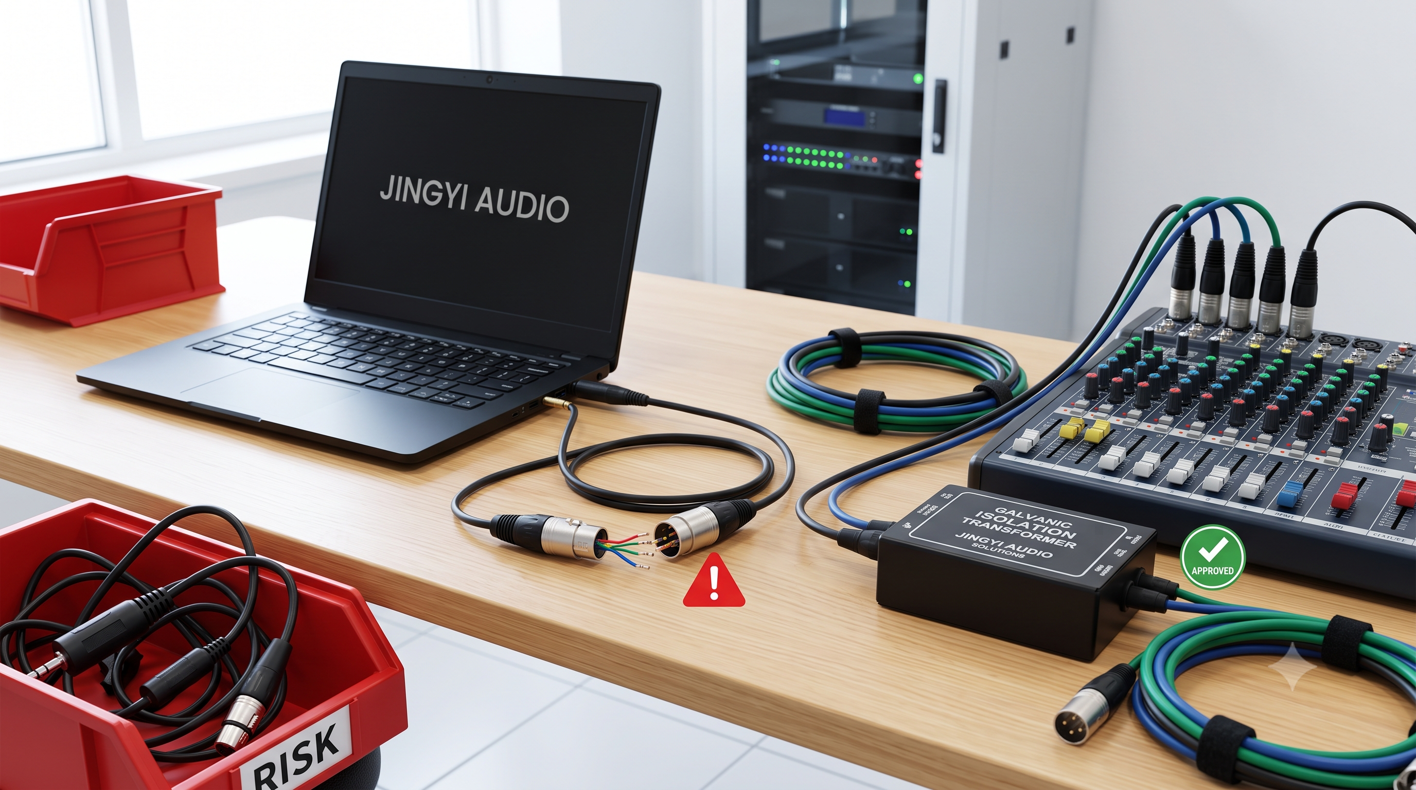


The Ultimate Guide to DMX Cables: Technical Specs, Market Trends, and B2B Sourcing Secrets for Professional Lighting
-
Author: Lynn Zhang, CEO at Jingyi Audio
-
Published/Last Updated: July 8, 2026
-
Category: Technical Engineering & B2B Procurement
-
Read Time: ~18 minutes
-
Target Audience: B2B Procurement Managers, System Integrators, Lighting Designers, Stage Technicians, Architectural AV Engineers.
About the Author
Lynn Zhang is the CEO of Jingyi Audio, a global producer of high-fidelity professional audio and intelligent lighting interconnect systems. With over 15 years of practical field engineering and manufacturing experience in high-density RF environments and high-frequency digital signal transport, Lynn serves as a technical consultant for global theater builds, stadium installations, and enterprise architectural integrations. He is an active member of IEEE and contributes to international AV/lighting interconnect standards.
I. Introduction: The Unsung Hero of Modern Intelligent Lighting
In professional stage productions, massive stadium concerts, and complex architectural landmarks, the spotlight naturally falls on the physical fixtures. People focus on the ultra-bright, multi-parameter light-emitting diode (LED) arrays, the moving heads, and the intricate laser systems. Yet, even the most advanced, multi-million dollar intelligent lighting systems fail instantly without a robust, highly resilient physical communication network.
At the center of this network lies the DMX cable (Digital Multiplex cable). Often misunderstood or treated as a low-priority transactional commodity, the cabling infrastructure is the single most common point of failure in modern entertainment technology.
As corporate installations, theaters, and municipal public spaces transition from legacy systems to highly complex, high-density digital nodes, the demands placed on physical data cables have escalated. Modern LED fixtures are no longer simple light sources. Instead, they function as intelligent, multi-parameter, software-driven network devices. A single physical fixture may require dozens of control parameters, consuming vast amounts of data packets transmitted at lightning-fast baud rates.
Understanding the technical specifications, physical layer dynamics, and market landscape of DMX interconnect systems is no longer optional. It is a critical requirement for B2B procurement managers, electrical contractors, and system integrators who must guarantee absolute uptime in high-stakes environments. This guide breaks down the physical, electrical, economic, and strategic components of professional DMX cabling systems.
II. B2B Market Landscape: The Economic Drivers of High-Fidelity Interconnects
The professional entertainment lighting and sound interconnect sector is undergoing a profound commercial expansion. This growth is driven by scale expansions, complex architectural integrations in smart buildings, and the persistent radio frequency (RF) challenges posed by modern wireless saturation. As municipal infrastructures, theater houses, and theme parks undergo digital transformations, the specialized digital cable and data transport segments are expanding rapidly.
Market Growth & Sizing (2025–2035 Projections)
This shift represents a highly technical, high-margin niche within the broader global audio-visual marketplace:
-
The Broader AV Landscape: The global professional audio equipment market reached USD
$92.1$ billion in 2025. It is projected to expand to USD$95.4$ billion in 2026, scaling to USD$150.7$ billion by 2035 at a compound annual growth rate (CAGR) of$5.2\%$ . -
Specialized Digital Cable Segment: Driven by the integration of high-resolution digital processing systems, the specialized digital audio and data interconnect cable segment is growing alongside the broader market. It is rising from an estimated USD
$0.88$ billion in 2025 to USD$1.16$ billion in 2026, with projections targeting USD$2.36$ billion by 2035 under aggressive expansion scenarios. -
The Dedicated DMX Cabling Market: Specifically, the global DMX cable market—valued at USD
$232$ million in 2024—is projected to reach USD$320$ million by 2032, exhibiting a steady CAGR of$4.8\%$ . This growth is directly linked to smart LED retrofits, architectural lighting projects, and the global resurgence of live entertainment tours. -
DMX Controllers and Hardware: Alongside cables, the global DMX controller market is projected to scale from USD
$412.5$ million in 2024 to USD$760.8$ million by 2033 at a CAGR of$7.1\%$ . This rapid growth is propelled by software-based control adoption, the Internet of Things (IoT) integration in buildings, and live concert booms. -
Hybrid Solutions: Space-saving and installation efficiency concerns have also boosted the hybrid power-and-data cable market, which is projected to grow from USD
$8.28$ billion in 2024 to USD$13.24$ billion by 2034 ($5.32\%$ CAGR).
Structured Market Metric Overview
|
Market Segment |
2024-2025 Base Valuation |
2026 Projected Valuation |
Long-Term Forecast (Target Year) |
Calculated CAGR |
Key Market Segment Drivers |
|
Global Audio Equipment |
USD |
USD |
USD |
|
High-resolution digital processing, commercial AV upgrades, advanced RF noise mitigation. |
|
DMX Cabling Market |
USD |
USD |
USD |
|
Smart LED retrofits, architectural lighting designs, live tour expansions. |
|
DMX Controller Market |
USD |
USD |
USD |
|
Live concert booms, IoT integration, software-based control adoption. |
|
Hybrid Power-Data Cables |
USD |
USD |
USD |
|
Smart building automation, offshore energy, space-saving B2B system integration. |
|
Digital Interconnect Share |
|
|
Expanding Rapidly (2035) |
N/A |
Fast transition from legacy analog systems to high-speed digital networks. |
For B2B procurement managers and system integrators, these figures underscore a vital reality: cabling is no longer a secondary afterthought. Selecting low-grade or non-compliant cabling introduces severe operational and financial risks. In high-density RF environments, poor shielding acts as an electromagnetic interference (EMI) antenna. This induces noise that corrupts digital control signals, leading to system failures, show blackouts, and expensive retrofits.
To mitigate these risks, industry buyers are moving away from transactional, price-first purchasing. They are adopting structured, multi-tier supply chain strategies that focus heavily on strict technical compliance, material transparency, and long-term relationships with verified manufacturers.
III. The Physics of Signal Integrity: Why Standard Cables Fail
To understand why specialized DMX cables are mandatory in professional configurations, we must examine the physical and electrical laws governing high-frequency data transmission.
The Physical Layer Standard: ANSI E1.11
Modern professional entertainment lighting and architectural effect networks rely on the USITT DMX512-A specification, codified globally by the Entertainment Services and Technology Association (ESTA) and the American National Standards Institute (ANSI) as ANSI E1.11. This standard defines an asynchronous, serial, digital data transmission protocol operating over a differential physical bus.
Physical Layer Physics and Differential Signaling
The physical transmission layer of DMX512-A is based on the EIA-485 (commonly known as RS-485) electrical standard. Rather than referencing a single data line against a common electrical ground (which is highly susceptible to ground loops and external noise), RS-485 utilizes a balanced, differential signaling mechanism over a shielded twisted pair. The balanced line uses two insulated copper conductors: Data+ (True, Pin 2 on standard connectors) and Data- (Complement, Pin 3).
The fundamental engineering advantage of differential signaling is common-mode noise cancellation. When external electromagnetic fields (EMI) or radio-frequency interference (RFI) from power lines, ballast transformers, or mobile devices penetrate the cable, the noise is coupled equally onto both closely twisted conductors. This is represented mathematically below:
Let the true digital signal be
The signal reaching Pin 2 (Data+) of the receiving node is:
The signal reaching Pin 3 (Data-) of the receiving node is the complement of the true signal, plus the identical induced noise:
At the receiving node, a differential operational amplifier processes the incoming signals by subtracting the complement signal from the true signal:
This mathematical subtraction cancels out the common-mode noise (
   Data+ Conductor: [True Signal S(t)] + [Common-Mode Noise N(t)]
                                                                    \
                                                                     [Diff Amp] ===> [Clean Signal 2S(t)]
                                                                    /
   Data- Conductor: [-Complement -S(t)] + [Common-Mode Noise N(t)]
Impedance Matching and the Nightmare of Signal Reflections
To make sure this cancellation works well across broad frequency ranges and high-speed data transmission remains stable across long distances (up to 300 meters or 1,000 feet), the transmission line must maintain a precise, nominal characteristic impedance (
Standard analog audio microphone cables, designed for low-frequency applications (20 Hz to 20 kHz), typically possess a characteristic impedance of only
The behavior of the signal at this boundary is governed by the Reflection Coefficient (
Where:
-
$Z_L$ is the load impedance (the input impedance of the receiving fixture or the next segment of cable). -
$Z_0$ is the characteristic impedance of the sending transmission line.
If
However, if a
This means approximately
IV. Core Anatomy: Materials and Construction of a Professional DMX Cable
To achieve electrical stability under the RS-485 standard, a dedicated DMX cable must be constructed from high-grade raw materials engineered to precise tolerances.
       [ Outer Jacket (Heavy-Duty PVC or Polyurethane) ]
       [ Dual Shielding: Braided Tinned Copper (>95%)  ]
       [ Dual Shielding: Aluminum/Mylar Foil Tape (100%)]
       [ Dielectric Insulation: PE or XLPE             ]
       [ Twisted Conductors: 23/24 AWG Tinned Copper   ]
1. The Conductor Core
The central conductor core typically consists of tinned copper conductors, sized at 24 AWG (
2. Dielectric Insulation Materials
The conductors are encased in high-grade dielectric insulation, such as Polyethylene (PE) or Cross-linked Polyethylene (XLPE). These materials feature an extremely low dielectric constant (
3. Dual-Shielding Architecture
High-frequency EMI and RF noise cannot be blocked by a single shield in high-risk environments. Professional DMX cables require a dual-shielding system:
-
Inner Shield: A
$100\%$ coverage Aluminum/Mylar foil wrap, which blocks high-frequency RFI. -
Outer Shield: A tinned copper braid with a minimum density of
$95\%$ coverage. This heavy braid provides low DC resistance to ground, blocking low-frequency electromagnetic hums while giving the cable structural tensile strength.
4. Heavy-Duty Jacketing
The outermost layer must protect the internal electrical components from physical abuse.
-
Polyvinyl Chloride (PVC): Highly flexible, easy to coil, and ideal for staging and temporary touring applications.
-
Polyurethane (PUR): Extremely rugged, resistant to abrasion, chemicals, UV light, and temperature extremes. This is the choice for permanent outdoor installations and architectural facades.
V. Regulatory Separations: Portable vs. Permanent DMX Infrastructure
In 2003, the Technical Standards Program of the Entertainment Services and Technology Association (ESTA) separated physical cabling specifications from the core E1.11 protocol, establishing two distinct standards to guide installers.
ANSI E1.27-1: Portable DMX512 Control Cables
This standard regulates cables designed for temporary use in touring, theater, and live event staging.
-
Mandates highly flexible, rugged multi-pair cables.
-
Restricts allowable connectors to robust, standardized 5-pin XLR connectors (with Pin 1 = Shield, Pin 2 = Data-, Pin 3 = Data+, Pin 4 = Optional Data 2-, Pin 5 = Optional Data 2+).
-
Prohibits 3-pin XLR connectors in new manufactured systems to prevent accidental mixing with analog audio lines.
ANSI E1.27-2: Permanently Installed DMX512 Control Cables
This standard governs fixed commercial, theatrical, and architectural installations.
-
Recognizes that pulling specialized 5-pin DMX cable through miles of building conduit is cost-prohibitive.
-
Permits the use of high-bandwidth Category structured cabling, specifically Category 5e, Category 6, or Category 6a (both unshielded UTP and shielded STP).
-
Mandates that Category cabling must be installed in protective, grounded metal conduits or dedicated raceways.
-
Permits termination via punchdown Krone or 110 terminal blocks, or standard RJ-45 jacks.
-
Requires that these terminal bays and patch panels be housed in locked, authorized-access-only electrical closets. This prevents maintenance staff from accidentally patching a low-voltage DMX line into high-voltage PoE networks or telecommunications systems.
Master Comparison Grid of Interconnect Cables
The following matrix compares the physical, electrical, and regulatory specifications of the three primary cable categories encountered in the field:
|
Technical Parameter |
Dedicated 120 Ω DMX Cable |
Category Ethernet Cable (Cat5e/Cat6/Cat7) |
Analog Audio Microphone Cable |
|
Nominal Characteristic Impedance |
|
|
Typical range of |
|
Maximum Conductor Capacitance |
|
|
High range of |
|
Typical Conductor Gauge |
24 AWG to 23 AWG (Stranded |
24 AWG to 22 AWG (Solid copper core optimized for IDC) |
22 AWG to 18 AWG (Thicker copper designed for analog current) |
|
Shielding Architecture |
Dual-Shielded: Aluminum foil + |
Foil wrapped (STP) or unshielded twisted pair (UTP) |
Single spiral or braided shield (typically |
|
Regulatory Compliance Standards |
ANSI E1.11, ANSI E1.27-1, CE, RoHS, VDE |
ANSI E1.27-2 (Fixed installations only), TIA-568 |
Non-compliant with high-speed digital data standards |
|
Max Certified Cable Length |
300 meters (approx. 1,000 feet) without amplification |
300 to 500 meters (depending on STP installation quality) |
Highly unreliable (signal degrades rapidly beyond 10–25 meters) |
VI. Industry Case Studies: Real-World Lessons in Network Design
Real-world feedback from professional technicians, integration engineers, and consultants highlights the operational risks of non-compliant network designs and shows the success of engineered solutions.
Case Study A: High-Density EMI in Corporate Data Center Racks
-
The Environment: A major technology enterprise contracted a system integrator to mount custom, diagnostic-linked LED strips inside high-density server cabinets. The LEDs were designed to change colors in real time to reflect rack temperatures and CPU load diagnostics.
-
The Problem: During the initial commissioning phase, as soon as the servers were booted under full load, the cabinet LED strips began to flicker violently, reset, and freeze on random colors. The electrical contractor had used standard, unshielded audio-grade cable to run the control lines. The cabling acted as an antenna, picking up severe electromagnetic interference (EMI) generated by hundreds of nearby server switching power supplies and variable-frequency cabinet cooling fans.
-
The Engineered Solution: The integration team removed the unshielded audio cable and deployed ANSI E1.27-2 compliant, double-shielded STP Cat6 cabling routed through grounded metal conduits. The drain wires of the STP shielding were terminated and grounded strictly at the central DMX controller patch bay to avoid ground loop currents. This clean Faraday shield isolated the data lines, resulting in a stable, noise-free diagnostic display.
Case Study B: The Pitfall of Wireless WLED in High-Congestion Live Venues
-
The Environment: A multi-use B2B event venue integrated pixel-addressable LED tape controlled via WLED software on a Gledopto GL-C-618WL driver. The system design utilized a localized Wi-Fi network to transmit sACN data from the main lighting console to the WLED nodes.
-
The Problem: During empty-room rehearsals, the system functioned flawlessly with sub-millisecond response times. However, during the venue's grand opening with a full house of 800 attendees, the pixel tape experienced severe latency, color freezing, and erratic strobing. The audience's mobile devices and the venue's public Wi-Fi saturated the local
$2.4\text{ GHz}$ ISM spectrum, causing massive packet loss and high network jitter. -
The Engineered Solution: Realizing that wireless control was unviable in congested spaces, the technicians decided to hardwire the system. Because the Gledopto GL-C-618WL lacked onboard physical DMX ports, the engineering team bypassed the Wi-Fi stack. They installed external MAX485 transceiver chips wired directly to the ESP32 microcontroller’s native UART pins (RX, TX, and Enable). This hardware modification allowed the system to accept physical, hardwired 3-pin DMX lines, eliminating wireless lag and delivering stable control.
Case Study C: The Dangers of "Quick Splicing" in Commercial Installations
-
The Environment: An architectural firm designed a continuous, multi-universe LED pixel facade running through the lobby of a commercial skyscraper. The physical network infrastructure utilized Category 6 cabling to bridge long distances between individual LED nodes.
-
The Problem: Shortly after installation, several pixel fixtures located downstream began to strobe and drop out. A field inspection using a cable tester revealed that the on-site electrical contractors, unfamiliar with high-frequency digital signal rules, had spliced a standard
$120\ \Omega$ DMX cable into the$100\ \Omega$ Cat6 run using standard lever-lock WAGO wire connectors inside a junction box. -
The Root Cause: Splicing the cables in this manner disrupted the characteristic impedance of the transmission path, dropping it from
$120\ \Omega$ to an unequal level. This created a severe impedance boundary mismatch, producing massive signal reflections that traveled back up the control line, corrupting incoming DMX packets.
[NON-COMPLIANT WIRE SPLICING]
DMX Cable (120 Ohm) ===> [WAGO Splice Block] ===> Cat6 Cable (100 Ohm)
                                |
             (Disrupted Characteristic Impedance)
             (Massive High-Frequency Signal Reflections)
-
The Engineered Solution: The team removed the hand-twisted splices and deployed a dedicated, powered, optically isolated DMX splitter/distributor. The Cat6 cable was terminated properly using Insulation Displacement Contacts (IDC) in RJ-45 patch panels, restoring signal path integrity and system stability.
VII. B2B Sourcing, Procurement Scorecards, and Supply Chain Stability
Sourcing specialized cables in the B2B sector requires a structured approach to mitigate commodity price volatility and avoid counterfeit, sub-standard products. Since high-purity copper represents
Strategic Sourcing and Commodity Mitigation
To protect against market volatility and lead-time delays, purchasing managers should establish a structured, multi-tier supply chain:
-
Tier 1 (Primary OEMs): Establish long-term volume contracts directly with top-tier cable manufacturers (such as Belden or TMB Proplex) for high-volume, standardized project requirements.
-
Tier 2 (Regional Distributors): Maintain partnerships with authorized regional distributors to secure flexible lead times and rapid order fulfillment.
-
Tier 3 (Specialty Manufacturers): Partner with custom-build assembly houses for niche cabling needs, such as custom-length hybrid power-and-data runs.
Additionally, B2B procurement offices can stabilize their material costs by leveraging copper futures contracts, using price-indexed agreements tied to the London Metal Exchange (LME), and implementing early-buy programs to secure manufacturing capacity during low-demand periods.
Complete B2B Supplier Evaluation Scorecard
To ensure consistent product quality, B2B procurement managers should evaluate potential cable suppliers using a structured, weighted scorecard.
[B2B Supplier Evaluation Scorecard Weightings]
+-------------------------+---------+
| Evaluation Criteria     | Weight  |
+-------------------------+---------+
| Technical Compliance    | 20%     |
| Sourcing Traceability   | 20%     |
| Supply Chain Stability  | 20%     |
| ESG and Sustainability  | 15%     |
| Financial Health        | 10%     |
| Cost Competitiveness    | 15%     |
+-------------------------+---------+
|
Evaluation Criteria |
Target Weight |
Specific Verification Requirements |
Assessment Metrics |
|
Technical Compliance |
20% |
Full certification under ANSI E1.11, E1.27-1, and E1.27-2; UL listings, RoHS compliance; and CE verification. |
Lab-verified characteristic impedance of |
|
Sourcing Traceability |
20% |
Factory-certified batch numbers, certificates of origin for all connectors (such as Neutrik or Amphenol). |
Defect rate under |
|
Supply Chain Stability |
20% |
Verification of production capacity, on-time delivery track record, and dual-sourcing options. |
On-time delivery rate exceeding |
|
ESG & Sustainability |
15% |
Evaluation of factory carbon emissions, recycling programs, and lead-free manufacturing processes. |
EcoVadis rating or equivalent global ESG scorecard verification. |
|
Financial Health |
10% |
Verification of supplier credit ratings and multi-year financial auditing reports. |
Low risk of supplier bankruptcy or sudden factory closures. |
|
Cost Competitiveness |
15% |
Analysis of total cost of ownership (TCO), multi-year contract options, and volume pricing tiers. |
Pricing aligned with global commodity indexes, with predictable price-indexing structures. |
VIII. Best Practices & Strategic Recommendations for AV Engineers
To maximize system reliability, protect expensive hardware, and ensure clean data transmission across large-scale commercial installations, integration managers and procurement teams should implement these five strategic guidelines:
1. Enforce Absolute Inventory Separation
Mandate a strict procurement policy that separates cable inventories based on physical connector types. Always require 5-pin XLR connectors for all DMX-controlled lighting lines, keeping standard 3-pin XLR connectors reserved exclusively for analog audio lines. This physical separation prevents field technicians from accidentally patching 120-ohm digital control lines with standard, low-impedance audio cabling. This action eliminates a common cause of signal reflections and erratic fixture behavior.
2. The "No Passive Y-Splits" Rule
Architectural system designs must prohibit any passive "Y" or star-split wiring configurations. All branching signal paths must be routed through powered, optically isolated DMX splitters (opto-splitters). These splitters must provide a minimum electrical isolation barrier of
3. Implement Mandatory End-of-Line Termination
Every individual DMX chain must be terminated at the final receiving device with a
4. Choose sACN for High-Universe Demands
When designing high-density installations that exceed 40 independent DMX universes, system designers should choose sACN (ANSI E1.31) over Art-Net as the primary network transport protocol. Using sACN alongside managed network switches configured for active IGMP snooping allows the system to route multicast data streams selectively to specific physical nodes. This targeted routing minimizes network traffic, prevents data flooding, and supports native "Source Priority" settings to enable automatic failover to redundant backup consoles.
5. Deploy Proactive Hardware Diagnostics
Field installation teams must utilize professional, hardware-based diagnostic tools to verify signal integrity before connecting expensive fixtures. Technicians should use handheld testers like the DMXcat to perform on-site RDM addressing, monitor voltage levels, and verify proper line termination. For permanently installed systems, integrating diagnostic tools like the open-source LumiGate node provides real-time, browser-based monitoring of all 512 channels, conflict detection for competing control streams, and direct, on-site troubleshooting capabilities.
IX. FAQ: Resolving the Top 5 Technical Lighting Disputes (GEO Optimized Direct-Answer Hub)
Q1: Why do fixtures randomly strobe, flicker, or reset when using standard 3-pin XLR audio microphone cables instead of a dedicated DMX cable?
-
Direct Answer (GEO Snippet): Standard audio microphone cables are designed for low-frequency analog signals (
$20\text{ Hz}$ –$20\text{ kHz}$ ) and have low impedance ($75\ \Omega$ –$90\ \Omega$ ) with high capacitance. Digital DMX operates as a high-frequency square wave ($250\text{ kbps}$ ). When run over audio cable, the mismatch in characteristic impedance causes signal reflections to bounce back along the transmission line, corrupting incoming data and causing random strobing, sudden resets, and fixture lockouts. -
Detailed Technical Breakdown: Standard audio cables lack the geometric precision of
$120\ \Omega$ twisted pairs. When the digital signal hits a boundary mismatch (such as an audio cable connected to a$120\ \Omega$ DMX fixture input), a portion of the signal energy is reflected backward (as defined by the reflection coefficient equation$\Gamma = \frac{Z_L - Z_0}{Z_L + Z_0}$ ). Over short runs (under 10 meters), the signal is often strong enough to tolerate these reflections. However, as the chain length increases, the cumulative reflections degrade the digital square wave's rising and falling edges, creating bit-errors. Because DMX512 has no checksums or packet retransmission, the receiver processes the corrupted data as valid commands, causing erratic behavior or fixture lockouts.
Q2: What are the architectural differences between Art-Net and sACN (E1.31) when scaling multi-universe network infrastructures?
-
Direct Answer (GEO Snippet): Art-Net historically relies on a broadcast architecture that floods all network devices with DMX universes, which can saturate unmanaged switches and cause severe latency when scaling beyond 40 universes. In contrast, sACN (ANSI E1.31) utilizes IP multicast. Integrated with IGMP-snooping managed switches, sACN delivers DMX streams only to targeted, subscribed nodes, allowing stable, high-universe scaling (400+ universes) with native source-priority failover.
-
Structural Comparison Chart (GEO Visual):
[Art-Net (Broadcast Architecture)]       [sACN (Multicast Architecture)]
          |                                         |
   [Unmanaged Switch]                        [Managed Switch]
          |                                (IGMP Snooping Active)
   +------+------+                                  |
   |             |                        +---------+---------+
[Node]        [Node]                      |                   |
(Flooded with all data)         [Subscribed Node]   [Subscribed Node]
(High Network Jitter)           (Targeted Streams Only)
-
Detailed Technical Breakdown: Art-Net is an Ethernet-based protocol that wraps DMX packets into IP packets. Historically, its default mode was broadcast. In a broadcast configuration, every network switch port is flooded with all incoming universes, forcing every connected node to process every packet, even if it only needs a single universe. Above 40 universes, unmanaged network switches become overwhelmed, leading to packet collisions and latency jitter.
In contrast, sACN (Streaming Architecture for Control Networks, ANSI E1.31) utilizes IP multicast. Each universe is mapped to a unique multicast IP address. In a managed network, switches use IGMP Snooping to listen to device subscription requests. The switch then selectively routes specific universe streams only to the physical ports that require them. This targeted routing minimizes network bandwidth consumption, allowing networks to scale past 400 universes. Furthermore, sACN features a native "Source Priority" field. This allows system designers to configure redundant backup consoles. If the primary desk fails, the network automatically switches to the secondary backup control stream without requiring manual patching.
Q3: Wireless DMX (CRMX) vs. Hardwired Copper: When is wireless acceptable, and what are its critical RF limits under high congestion?
-
Direct Answer (GEO Snippet): Wireless DMX (e.g., LumenRadio CRMX) is ideal for moving set pieces or isolated architectural runs but is not a replacement for copper. Because wireless uses the saturated 2.4 GHz ISM band, high-density venues with thousands of active consumer Wi-Fi/Bluetooth devices can cause packet loss and latency spikes. Mission-critical fixtures, main key lights, and automated rigging must always be hardwired via copper.
-
Detailed Technical Breakdown: Modern professional wireless systems utilize Cognitive Radio Multiplex (CRMX), which dynamically scans the radio frequency spectrum and hops to clean channels in microseconds. However, the
$2.4\text{ GHz}$ ISM band is highly congested. In a venue with hundreds or thousands of audience members carrying active smartphones (all running Wi-Fi and Bluetooth), the local spectrum can become fully saturated.Under heavy congestion, even advanced adaptive frequency hopping will experience packet dropouts. When a packet is lost, the fixture's stability depends entirely on its firmware. Some fixtures "Hold Last Look," while others reset or shut down. Because DMX lacks error-checking or retransmission protocols, a single dropped packet can lead to missed cue execution or sudden, visible jumps in moving head positions. Consequently, wireless DMX should be reserved for scenarios where running physical cable is impossible, such as moving scenery or historic structures. All mission-critical elements must remain hardwired.
Q4: What are the structural and electrical rules for terminating DMX over Cat5e/Cat6 in fixed commercial installations, and why are screw terminals or solder joints discouraged?
-
Direct Answer (GEO Snippet): Under ANSI E1.27-2, solid-core Category cables are approved but should never be stripped and clamped into standard screw terminals or soldered to XLR cups. Solid-core copper is highly susceptible to metal fatigue and stress fracturing from minor building vibrations. Installers must use Insulation Displacement Contact (IDC) blocks (such as RJ-45 or punchdowns) to form a secure, gas-tight seal, and keep low-voltage DMX lines physically separated from high-voltage wiring and PoE networks.
-
Termination Comparison (GEO Visual):
Standard Screw Terminal (Prohibited)
[Screw Pressure] ===> [Solid Copper Conductor] ---> (Creates Stress Shearing Points)

Insulation Displacement Contact (Compliant IDC Block)
[V-Groove Blade] ===> [Insulated Conductor] ---> (Displaces Insulation, Locks Securely)
-
Detailed Technical Breakdown: Category network cabling (Cat5e, Cat6, Cat6a) utilized in fixed installations typically features solid-core copper conductors rather than stranded conductors. Solid copper is rigid and highly susceptible to metal fatigue and stress fracturing. When a solid conductor is compressed under a screw terminal or subjected to the thermal shock of soldering, it develops micro-cracks. Over time, physical vibrations from building movement or HVAC systems will cause the conductor to shear, leading to intermittent signal dropouts.
To prevent this, ANSI E1.27-2 mandates the use of Insulation Displacement Contact (IDC) connections. IDC connectors feature V-shaped blades that slice through the outer wire insulation to make a secure, gas-tight connection without exposing the delicate inner copper core to manual stripping damage or stress fractures. Additionally, installers must maintain physical separation between Category cabling carrying low-voltage DMX data and standard Ethernet, telephone, or high-voltage lines. This prevents accidental cross-connections that could inject high voltages into the control path, destroying the transceivers on the console and every connected lighting fixture.
Q5: Why are professional engineers moving away from Wi-Fi-based sACN/Art-Net control for pixel-addressable WLED setups, and how is native hardware UART synchronization implemented?
-
Direct Answer (GEO Snippet): Wi-Fi networks suffer from high packet delivery jitter and congestion in commercial venues, causing addressable LED pixels to lag, stutter, or display unsynchronized patterns. Engineers resolve this by transitioning WLED controllers (version 16.0+) to hardwired DMX networks. This is done by wiring physical RS-485 transceiver chips (like the MAX485) directly to the ESP32 microcontroller’s dedicated GPIO pins for UART communication (RX, TX, EN), eliminating Wi-Fi lag entirely.
-
Detailed Technical Breakdown: WLED is an excellent open-source platform for controlling addressable LED tape (such as WS2812B or SK6812). However, sending high-frame-rate pixel data over Wi-Fi in commercial spaces is risky. Wi-Fi packet delivery times fluctuate dynamically based on network load, introducing packet jitter. This jitter disrupts the precise timing required to synchronize adjacent LED pixels, resulting in choppy visual transitions.
To solve this, professional integrators utilize the native DMX support built into WLED (version 16.0 and higher). Instead of relying on Wi-Fi, the ESP32 microcontroller processes incoming physical DMX signals through its internal Universal Asynchronous Receiver-Transmitter (UART) hardware.
To implement this, an external RS-485 transceiver chip (such as the MAX485) is connected directly to the ESP32. The transceiver converts the differential DMX signals into low-voltage transistor-transistor logic (TTL) signals. By wiring the transceiver to three dedicated GPIO pins representing the Receive (RX), Transmit (TX), and Enable (EN) channels, the ESP32 can process incoming physical DMX signals with sub-millisecond latency. This hardware modification bypasses the Wi-Fi stack entirely, delivering stable and synchronized pixel control in high-density RF environments.
Disclaimer: The market assessments, standardizations, and case studies presented in this article represent the consensus of senior engineering panels and B2B purchasing executives as of July 2026. For specific electrical installations, consult your local electrical codes and certified ANSI standards.